
System and method for storing energy in a nuclear power plant

a technology for storing energy and nuclear power plants, applied in nuclear elements, greenhouse gas reduction, lighting and heating apparatus, etc., can solve the problems of slow response of nuclear power plants to variations in the demand for power from the grid, high initial cost of investment in nuclear power plants, and serious impact on the potential to become the major source of electricity. , to achieve the effect of high turndown ratio, fast response and large capacity

Active Publication Date: 2010-08-12
RES FOUND THE CITY UNIV OF NEW YORK
View PDF14 Cites 12 Cited by
  • Summary
  • Abstract
  • Description
  • Claims
  • Application Information

AI Technical Summary

Benefits of technology

[0012]The invention provides for a system and method for equipping specific types of nuclear power plants with low cost storage that has a very high thermal efficiency. As a result of the invention, nuclear reactors will be able to operate cost-effectively at maximum capacity and will be able to compete with conventional fossil fueled power plants in their responsiveness to load changes over a wide range.
[0013]The system and method can utilize a high temperature heat transfer medium, e.g., hot helium (He), and can be used to provide heat for a steam power plant. A steam power plant can, in particular, be used as it has a high turndown ratio and provides a fast response. Of course, any device that can use heat to generate electricity may be substituted. To increase its suitability for variable operation, the size of the steam power plant can be enlarged to several times that of the nuclear reactor without increasing the size of the nuclear reactor itself.
[0019]The process may be capable of providing fast load following whenever needed by using sufficient storage and a steam power plant is configured for a high turndown ratio and fast response. The power-generating device may be capable of meeting a maximum variable load expected even when the load is larger than the rated capacity of the nuclear power plant, whereby the nuclear power plant is able to achieve a large capacity for short times using the stored heat.
[0037]The process may be capable of providing fast load following whenever needed by using sufficient storage and a steam power plant configured for a high turndown ratio and fast response.
[0038]The power-generating device may be capable of meeting a maximum variable load expected even when the load is larger than the rated capacity of the nuclear power plant, whereby the nuclear power plant is able to achieve a large capacity for short times using the stored heat.

Problems solved by technology

Nuclear reactors have a large thermal inertia, which slows their responsiveness to variations in the demand for power from the grid.
Their potential to become the major source of electricity is seriously affected by this limitation.
Additionally, the initial cost of investment in a nuclear power plant is high; therefore, they must be built to operate at full capacity as it is too costly to operate them at low loads.
Operating them at or below half-capacity is not economically attractive since halving the load nearly doubles the cost per KWh.
Another limitation on their functionality is that due to their thermal inertia, nuclear reactors can have a slow transient response.
As currently designed, nuclear power plants are unable to follow the variable demands of the grid because they are expensive to operate at intermediate loads and unsuitable for rapid load following.
Because they are used mostly for base power, the total contribution they can make to the grid is thereby limited.
While coal-fired steam power plants can respond to load changes quickly and can operate well with a load of only 13% of design capacity, they are more expensive to use for generating electricity during periods of partial load as they must be designed for maximum capacity.
Various energy storage devices have been proposed to solve this problem, but all of these proposals have limited efficiency (about 75%) and are expensive.
Furthermore, while storage systems have been proposed for solar thermal power plants (see Sargent & Lundy, “Assessment of Parabolic Trough and Power Tower Solar Technology Cost and Performance Forecasts”, SL-5641, (2002), the disclosure of which is hereby expressly incorporated by reference in its entirety), they are based on liquid heat transfer fluids and molten salts, which may be unsuitable for nuclear reactors.

Method used


Image

  • System and method for storing energy in a nuclear power plant
  • System and method for storing energy in a nuclear power plant

Examples


example

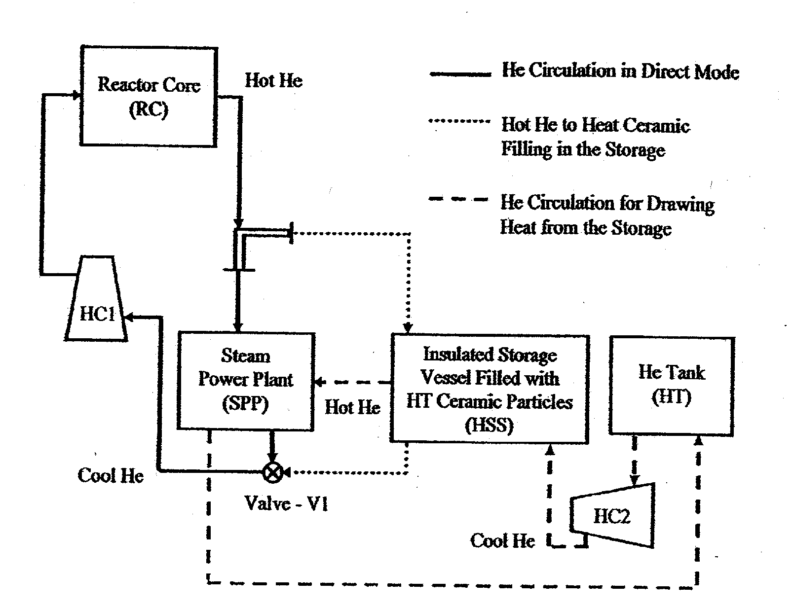
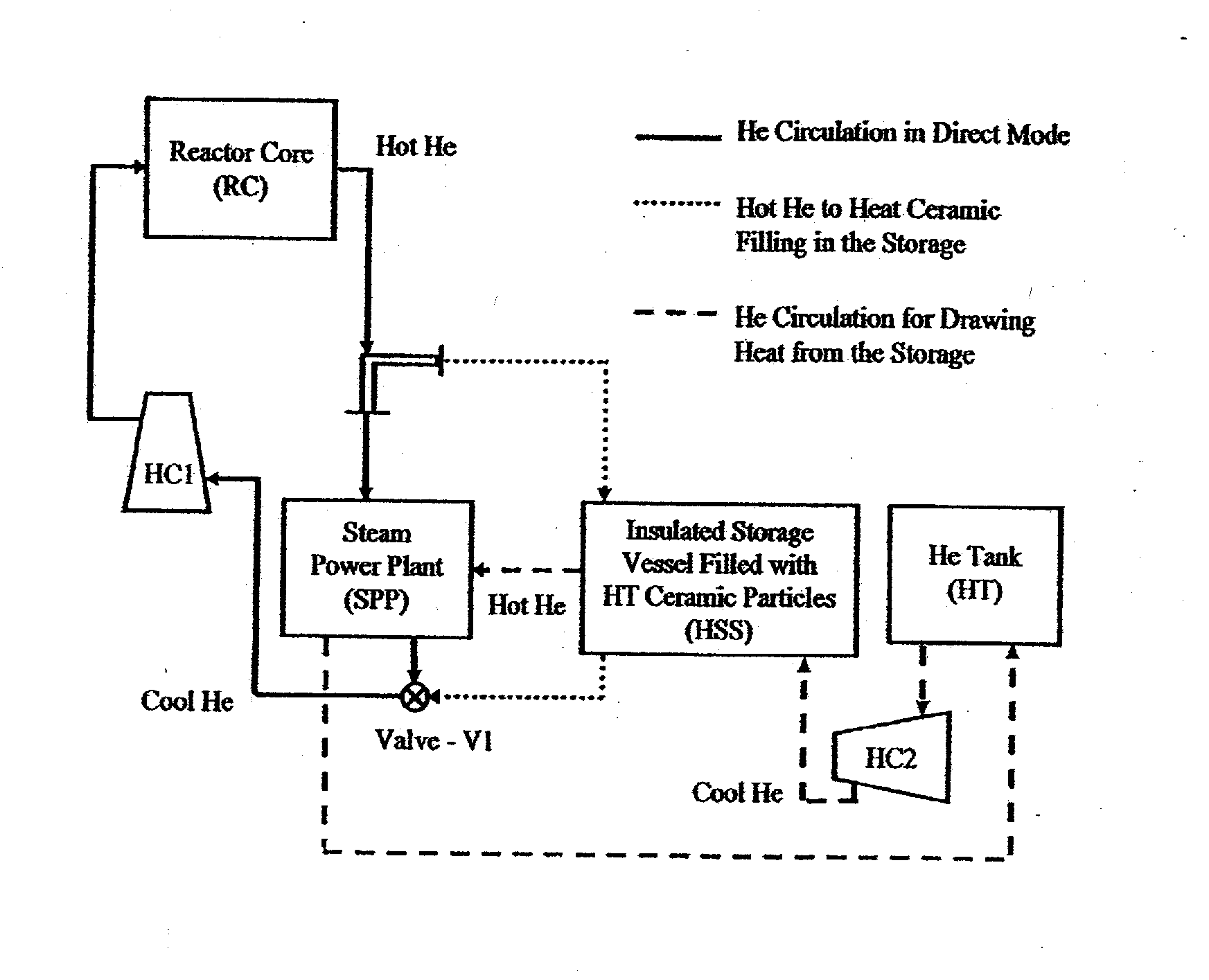
[0052]Consider a 250 MW high-temperature nuclear reactor in which the reactor core RC is cooled by circulating He under pressure. According to the invention, the hot He is used to raise or produce steam in a high-pressure, high-efficiency steam power plant SPP which has a fast response, a high turndown ratio and, can operate efficiently at 13% of capacity. Then, the gas is recycled cold to the reactor core RC. If the maximum capacity of the steam power plant SPP is increased four-fold to 1000 MW, 1000 MW can be delivered for short periods, even though the heat source is sufficient for only an average load of 250 MW. For load following, the output can be varied over the entire range, 150 to 1000 MW. For supplying intermediate power, the steam power plant SPP needs to be increased to 500 MW, operating 12-13 hours a day. In addition, it is assumed that 12 hours of storage might be optimal.

[0053]Assuming also that a steam power plant SPP requires 8000 BTU / KWh, 12 times that amount or 96...


PUM


Abstract

A method of storing heat includes moving a portion of a heated fluid from at least one reactor core to at least one tank having solid media, storing heat from the portion of the heated fluid in the solid media, and transferring the stored heat from the solid media to a fluid that can be used by a power plant to generate electrical energy. A system for storing heat in a nuclear power plant includes at least one tank comprising solid media structured and arranged to store heat and an arrangement structured and arranged to pass a first fluid through the at least one tank, transfer heat from the first fluid to the solid media, store the heat in the solid media, and transfer the heat from the solid media to a second fluid. This Abstract is not intended to define the invention disclosed in the specification, nor intended to limit the scope of the invention in any way.

Description

CROSS-REFERENCE TO RELATED APPLICATIONS[0001]The present application claims the benefit of U.S. Provisional Patent Application No. 60 / 834,736, filed on Aug. 1, 2006 under 35 U.S.C. §119(e), the disclosure of which is expressly incorporated by reference herein in its entirety.BACKGROUND OF THE INVENTION[0002]1. Field of the Invention[0003]The invention relates a system and method of equipping specific types of nuclear power plants with low cost storage that has a very high thermal efficiency.[0004]The invention also relates to systems and methods for operating nuclear reactors cost-effectively at maximum capacity so that nuclear plants will be able to compete with conventional fossil fueled power plants in their responsiveness to load changes over a wide range.[0005]The invention also relates to a storage system and method for a high-temperature gas-cooled nuclear reactor wherein the storage system or the method has a high efficiency (over 90%) and a low cost, allowing the nuclear re...

Claims


Application Information

Patent Timeline
Patent Type & Authority Applications(United States)
IPC IPC(8): G21C19/28
CPCF01K3/00F22B1/1823G21C19/28G21D1/006Y02E30/40G21D1/00Y02E30/00Y02E30/30
Inventor SHINNAR, REUELHIRSCH, ROBERT L.
Owner RES FOUND THE CITY UNIV OF NEW YORK
Learn More