METHOD OF STIMULATING SUBTERRANEAN FORMATION USING LOW pH FLUID

a subterranean formation and fluid technology, applied in the direction of sealing/packing, chemistry apparatus and processes, wellbore/well accessories, etc., can solve the problems of increasing the viscosity of the fluid, affecting the formation, and the effectiveness of conventional crosslinking agents in the presence of certain foaming agents, etc., to achieve excellent time-delay crosslinking, minimize permeability damage, and reduce the effect of permeability

Inactive Publication Date: 2010-08-12
BAKER HUGHES INC
View PDF54 Cites 19 Cited by
  • Summary
  • Abstract
  • Description
  • Claims
  • Application Information

AI Technical Summary

Benefits of technology

[0011]An aqueous well treatment fluid containing a guar gum derivative, an organic zirconate complex and a hydroxylated glycine and characterized by a low pH minimizes permeability damage,...

Problems solved by technology

The fluid is then pumped at rates and pressures that exceed the confining stresses in the formation, causing the formation to fail by inducing a fracture.
In addition, such agents typically increase the viscosity of the fluid.
In those instances where it is desired to use a non-gaseous foaming agent in order to treat a water sensitive formation, it has been found that conventional crosslinking agents are less effective in the presence of certain foaming age...

Method used


Image

  • METHOD OF STIMULATING SUBTERRANEAN FORMATION USING LOW pH FLUID
  • METHOD OF STIMULATING SUBTERRANEAN FORMATION USING LOW pH FLUID
  • METHOD OF STIMULATING SUBTERRANEAN FORMATION USING LOW pH FLUID

Examples


example 1

[0056]A gel was prepared by adding 7.5 ml of a polymer slurry containing the equivalent of 3.6 g of carboxymethyl guar having a degree of substitution (DS) of 0.17 to one liter of vigorously stirred tap water. The fluid was also treated with 1.0 ml of a 50% (by wt) solution of tetramethyl ammonium chloride and 5.0 ml of an acetic acid sodium acetate buffer designed for a pH of 4.5.

[0057]The speed of a Waring blender was adjusted to 1500 rpm and 250 grams of the gel was then poured into the blender. Blender jars were then inserted into the blender and mixing was started and a stable vortex was formed with the nut of the blades being visible. After approximately 1 minute, zirconium N,N-bis 2-hydroxy ethyl glycine (ZrBHEG) as crosslinking delaying agent was added and the pH of the solution was then recorded. Approximately 0.40 ml of a zirconium complex of alkanol amine in propanol, commercially available as Tyzor-223 from E.I. DuPont de Nemours and Company, was then injected into the b...

example 2

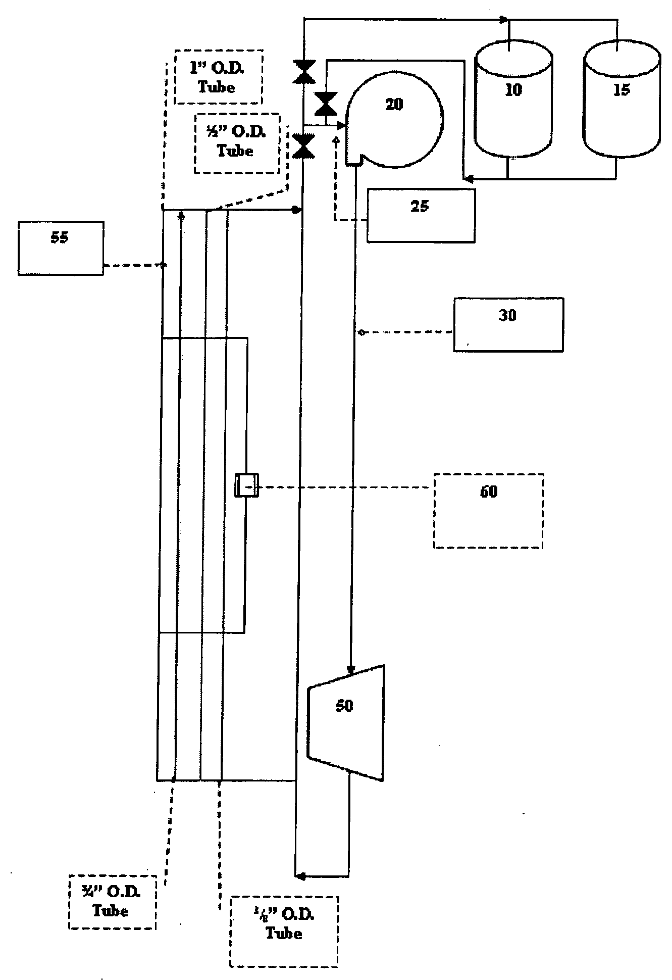
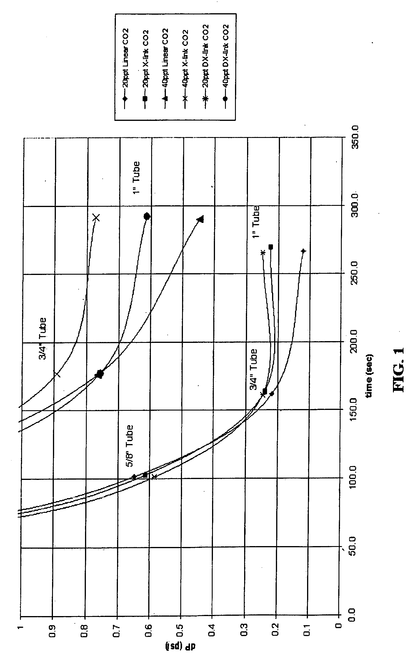
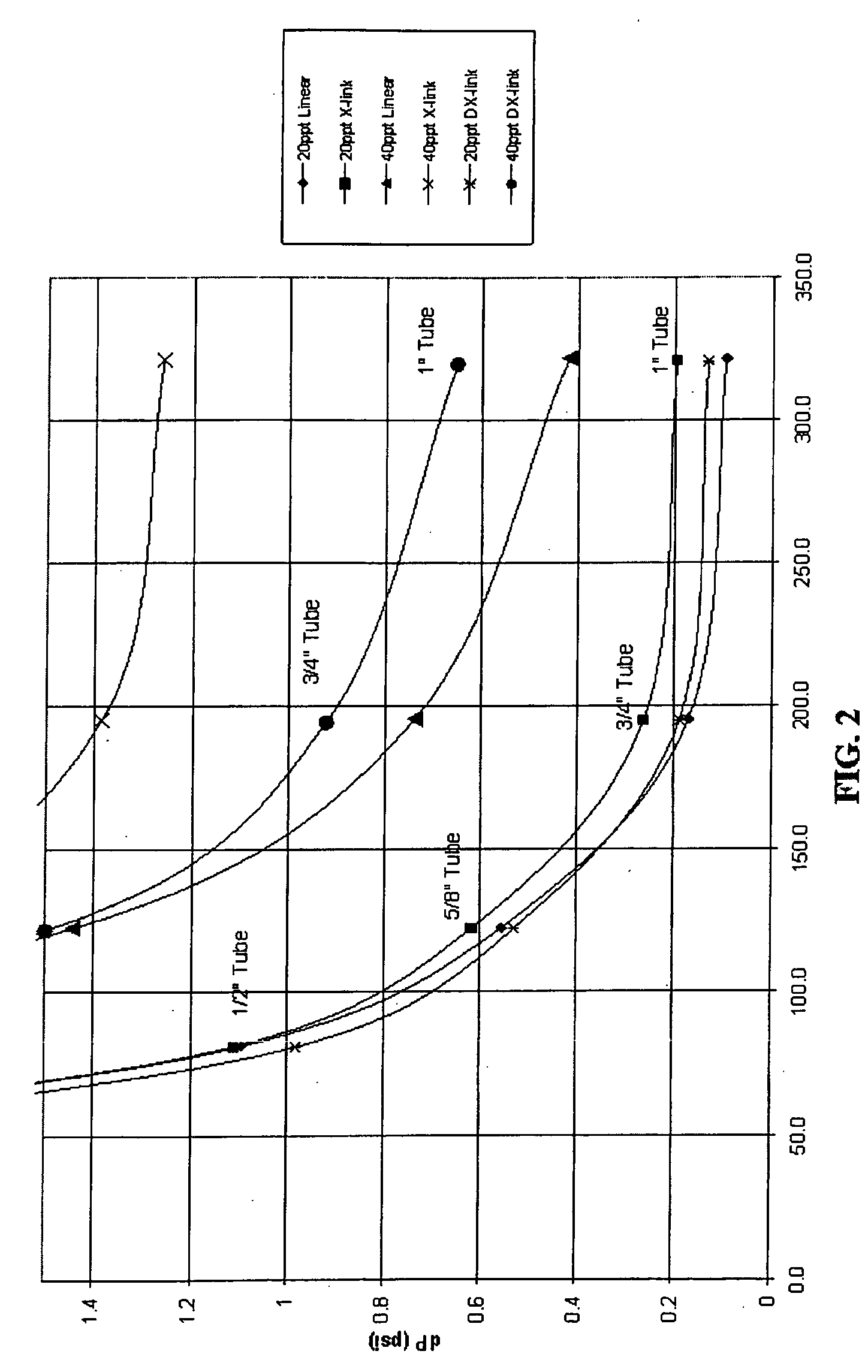
[0059]This Example illustrates the effectiveness of the delay agent to fluid friction pressure when injecting the fluid through a foam loop with multiple pipe sizes.

[0060]The crosslinking delay efficiency of an aqueous fluid prepared in accordance with the invention was determined using a single pass foam rheometer. To measure early time, the heated coil section was bypassed and run directly through the capillary viscometer section. Each of the five tubes of the capillary viscometer section had a pressure transducer to measure the differential pressure and to calculate n′, K and viscosity.

[0061]To create a baseline in order to compare the pressures, a liner gel with no crosslinker was run through the rheometer first. A 20 ppt and a 40 ppt gel were passed through the system with and without carbon dioxide. The next sets of tests were performed with the same gel concentrations but with optimized crosslinker loading. This provided the maximum upper and lower pressures through the rheom...

examples 3 and 4

below illustrate the rheological stability of fluids in the absence of a gas and thus present a means of optimizing the liquid phase components. The method used for these Examples is defined in the American Petroleum Institute's ANSI / API Recommended Practice 13 M entitled “Recommended Practice for the Measurement of Viscous Properties of Completion Fluids”, First Edition, 2004. The tests were conducted using an automated Fann 50 viscometer equipped with an R1B5 cup (radius=1.8415 cm; length=14.240 cm) and bob (radius=1.5987 cm; length=8.7280 cm) assembly.


PUM


Abstract

Hydraulic fracturing is conducted by use of a well treatment fluid which contains a guar gum derivative as viscosifying or gelling polymer, an organic zirconate complex of a zirconium metal and an alkanol amine as crosslinking agent and a hydroxylated glycine as crosslinking delaying agent. The fluid is characterized by a low pH, generally greater than or equal to 3.0 and less than or equal to 5.0.

Description

FIELD OF THE INVENTION[0001]The invention relates to a method of stimulating a subterranean formation penetrated by an oil or gas well by use of an aqueous crosslinkable fluid having a low pH which exhibits delayed crosslinking under downhole conditions.BACKGROUND OF THE INVENTION[0002]Hydraulic fracturing is the process of enhancing oil and / or gas production from producing wells or enhancing the injection of water or other fluids into injection wells. Typically, a fracturing fluid is injected into the well, passing down the tubulars to the subterranean formation penetrated by the wellbore. The fluid is then pumped at rates and pressures that exceed the confining stresses in the formation, causing the formation to fail by inducing a fracture. This fracture originates at the wellbore and extends in opposite direction away from the wellbore. As more fluid is injected, the length, width and height of the fracture continue to extend. At a point, the width increases so that propping agen...

Claims


Application Information

Patent Timeline
IPC IPC(8): C09K8/60
CPCC09K8/685C09K8/70C09K2208/26C09K8/90C09K8/887
Inventor LE, HOANG VANCARMAN, PAULGUPTA, D. V. SATYANARAYANA
Owner BAKER HUGHES INC
Why Eureka
Try Eureka