Heating device for liquid fuels and the like

Inactive Publication Date: 2010-08-19
ROBERT BOSCH GMBH
View PDF7 Cites 1 Cited by
  • Summary
  • Abstract
  • Description
  • Claims
  • Application Information

AI Technical Summary

Benefits of technology

[0004]In contrast, the heating device according to the present invention having the features described herein, the fuel injector according to the present invention having the features further described herein, and the component of a fuel-injection system according to the present invention having the features further described herein have the advantage of ensuring an advantageous heat source with reliable protection against overheating. In particular when heating liquid fuels, a reliable protection against overheating can be ensured since the surface temperature of the heating element is able to be restricted in order not to exceed the ignition temperature of a fuel, especially a fuel mixture.
[0008]It is also advantageous that an outer surface of the self-regulating heating element is at least partially coated with a protective layer. The protective layer may also be restricted to a portion of the outer surface that is susceptible to the action of fuel. The protective layer makes it possible to obtain higher resistance to the surrounding media, in particular diesel fuel containing fuel or water.
[0009]Furthermore, it is advantageous that the protective layer has solid pigment particles which improve the thermal conductivity of the protective layer. The solid pigments may essentially be formed by boron nitride, graphite and / or silicon carbide.
[0010]It is also advantageous that the self-regulating heating element is enclosed by the housing component. In this case it is also advantageous that the housing component is made from a heat-conductive plastic or composite. In addition, the housing component may be designed to be impact-resistant and temperature-resistant, so that protection of the heating element from chemical and mechanical damage is ensured. This also facilitates the handling of the heating element. In particular, damage during transport or installation is prevented.

Problems solved by technology

However, when such a known fuel injector is used in a fuel-injection system, the problem arises that, in particular, a starting behavior of an engine is disadvantageous.
This problem occurs especially when a mixture of gasoline and alcohol, a diesel fuel or a mixture of diesel and organic fuels is used as fuel.

Method used


Image

  • Heating device for liquid fuels and the like
  • Heating device for liquid fuels and the like
  • Heating device for liquid fuels and the like

Examples


Embodiment Construction

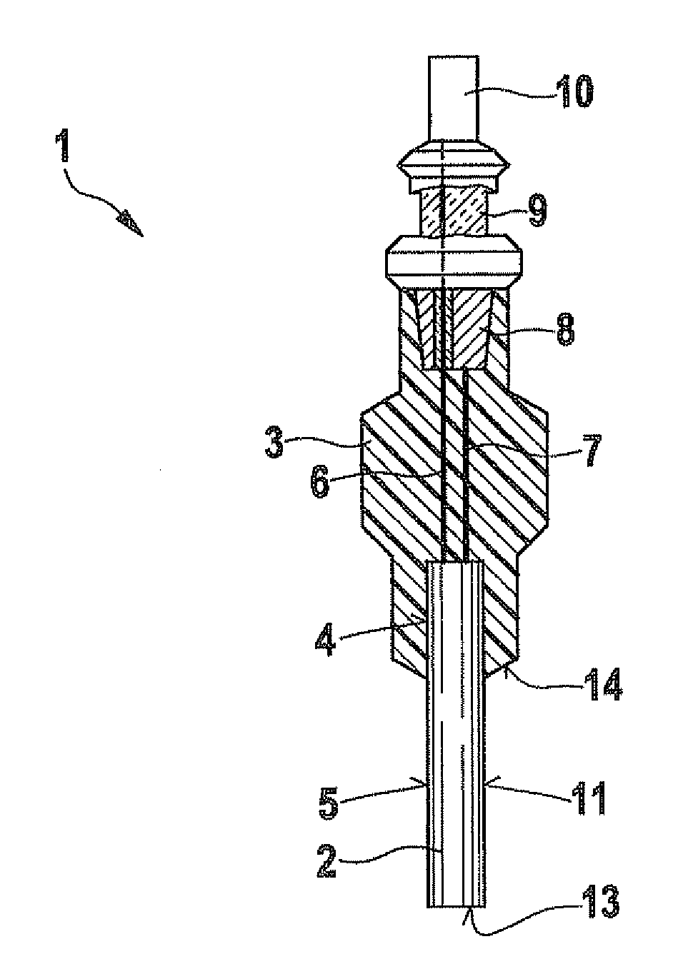
[0023]FIG. 1 shows a heating device 1 having a self-regulating heating element 2 according to a first exemplary embodiment of the present invention. Heating device 1 may be designed as heater for liquid fuels, in particular. The heating device is especially suitable for fuel-injection systems of mixture-compressing, externally ignited internal combustion engines or for air-compressing, self-igniting internal combustion engines, gasoline, diesel, a mixture of gasoline or diesel with other fuels, or the like being used. Alcohols, especially methanol or ethanol, or biological fuels, especially oils such as rapeseed oil, also may be used as fuel.

[0024]However, heating device 1 of the present invention is suitable for other applications as well.

[0025]Heating device 1 has a housing component 3, in which self-regulating heating element 2 is partially embedded. A contacting region 4 of heating element 2 is at least essentially surrounded by housing component 3, while a heating region 5 of h...


PUM


Abstract

A heating device, which is designed as a heater for liquid fuels, has a housing component and a heating element embedded in the housing component. The heating element is designed as a self-regulating heating element, so that protection against overheating is ensured.

Description

FIELD OF THE INVENTION[0001]The present invention relates to a heating system. More specifically, the present invention relates to a heater for liquid fuels, which is able to be integrated into a component of a fuel-injection system. Among other things, the heating device is suitable for a fuel injector of air-compressing, self-igniting internal combustion engines.BACKGROUND INFORMATION[0002]A fuel injector for an internal combustion engine is discussed in German patent document DE 40 05 455 A1. There, a piezoelectric actuating element for a valve needle is provided. Furthermore, a chamber filled with fuel is provided, which is sealed via a spring diaphragm, which simultaneously operates as restoring spring for the valve needle.[0003]In the fuel injector of DE 40 05 455 A1 the fuel is spray-discharged from the fuel-filled chamber when the valve needle is actuated. However, when such a known fuel injector is used in a fuel-injection system, the problem arises that, in particular, a s...

Claims


Application Information

Patent Timeline
IPC IPC(8): F02M61/00H05B3/02F02N19/04
CPCF02M31/125F02M53/06F02N19/04Y02T10/126H05B3/141H05B2203/027F23Q7/001Y02T10/12
Inventor SCHNEIDER, JENSCOUFFIGNAL, JEAN-MARCERNST, STEPHAN
Owner ROBERT BOSCH GMBH
Why Eureka
Try Eureka