Fiber separation using elusieve process

a fiber and elusieve technology, applied in the field of separating fiber, can solve the problems of restricting the applicability of high fiber ddgs, non-ruminant animals, generally less able to digest high fiber ddgs, and limited success of aspiration in recovering fiber, etc., and achieve the effect of being adaptabl

Active Publication Date: 2010-08-19
MISSISSIPPI STATE UNIV RES TECH
View PDF5 Cites 10 Cited by
  • Summary
  • Abstract
  • Description
  • Claims
  • Application Information

AI Technical Summary

Benefits of technology

[0068]In an embodiment, a process, device, or composition is readily adaptable to a modern ethanol production plant. For example, a process or devi

Problems solved by technology

For example, the typically high fiber content of DDGS restricts its applicability as a feed product.
Non-ruminant animals, however, are generally less able to digest high fiber DDGS.
The study showed limited success for aspiration in recovering fiber from DDGS and in recovering phytosterol compounds which are plant sterols that may be useful in lowering cholesterol levels.
Aspirating DDGS samples produced by the dry-grind ethanol process did no

Method used


Image

  • Fiber separation using elusieve process
  • Fiber separation using elusieve process
  • Fiber separation using elusieve process

Examples


example 1

Method of Removing Fiber from DDGS

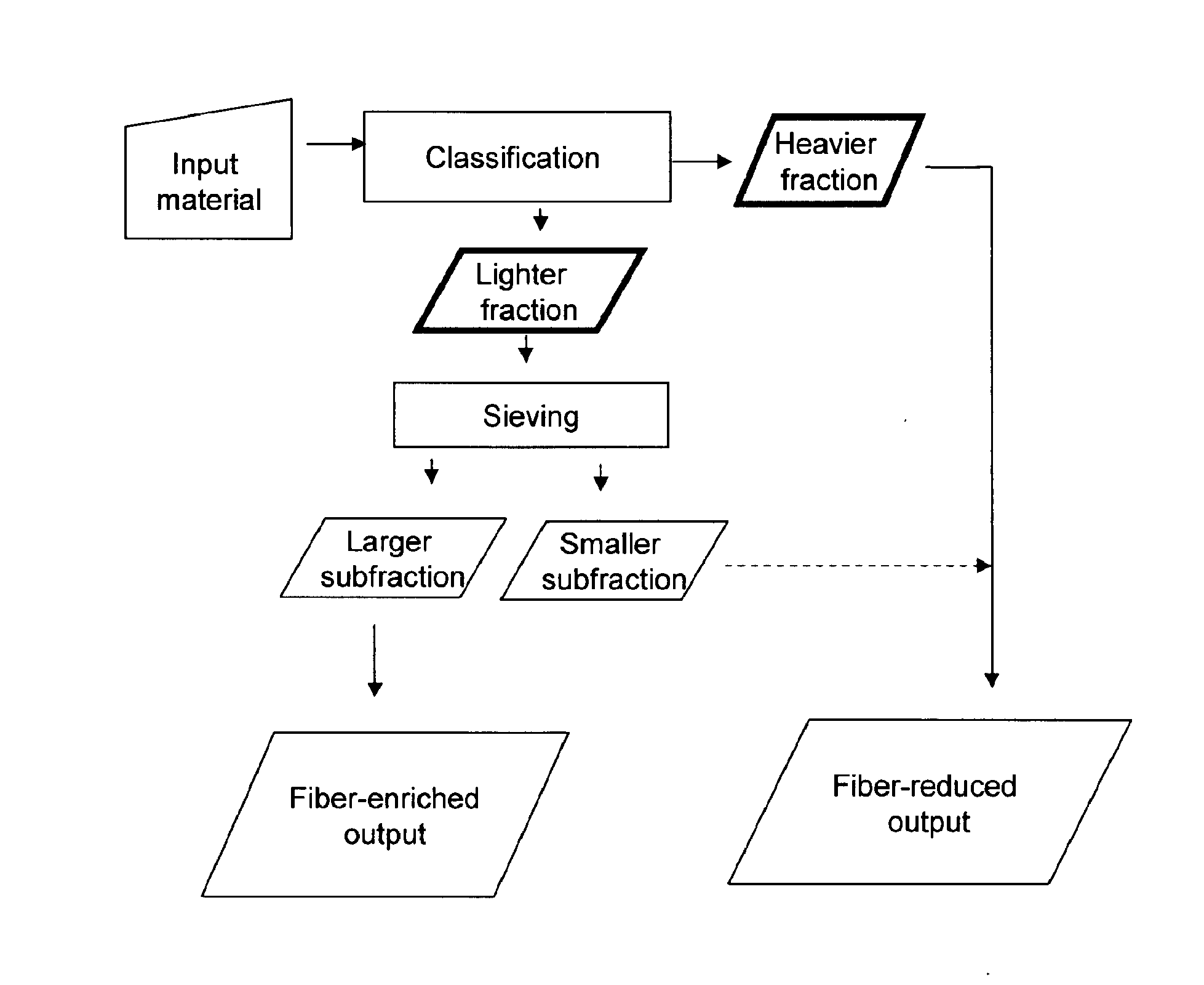
[0089]FIG. 4 illustrates a flow chart of a fiber removal process. Input material is first subjected to classification, such as by gravity air elutriation. This separates the input material into heavier and lighter fractions. The lighter fraction is then sieved into a larger subfraction and a smaller subfraction. The initial heavier fraction can be combined with the smaller subfraction from sieving to yield a fiber-reduced output. The larger subfraction from sieving yields a fiber-enriched output.

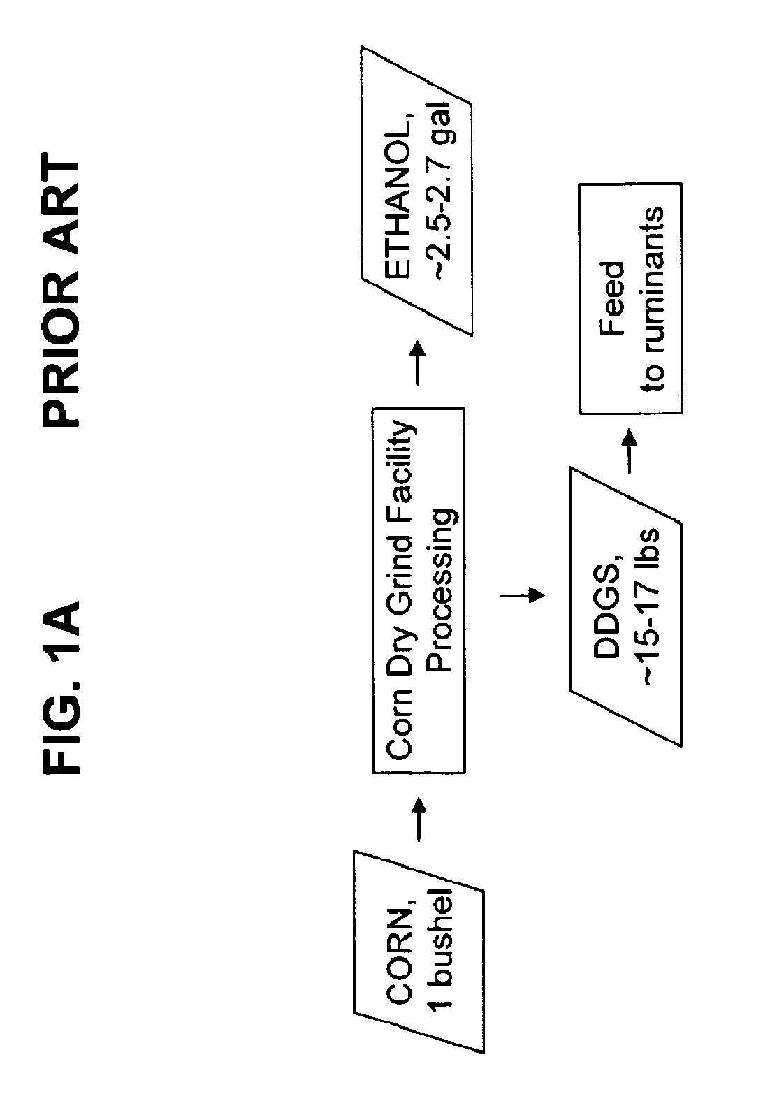
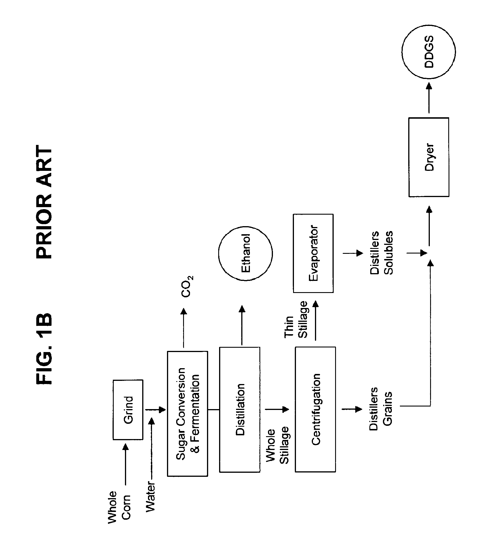
[0090]In a particular example, the input material is DDGS. DDGS is conventionally produced in an ethanol processing plant using the Dry Grind process. See FIG. 1. In an embodiment of the invention, the fiber content of conventionally produced DDGS is reduced to yield an enhanced DDGS. This enhanced DDGS can be used as feed product for non-ruminant agricultural animals, such as swine and poultry, in addition to still being suitable for ruminants. Additionally...

example 2

Elutriation Apparatus

[0101]See FIG. 6. An elutriation column 10 is connected to a fan or air blower 20 via an air inlet 30. A feeder 40 is connected to column 10 via a feeder inlet 50. Input material 60, comprised of light components and heavy components, is introduced to column 10 using feeder 40. Output residue or heavier fraction 70 collects at the bottom end of column 10. Output lighter fraction 80 is carried by fluid flow to one or more collection reservoirs 90. See also FIG. 7.

[0102]A feeder is used as known in the art. For example, the feeder can be a vibratory feeder, auger, hopper, conveyer, or dumper container optionally mechanized. Used in several examples herein, a preferred vibratory feeder is POWDERTEC 3090 Sample Mill. A blower used in several examples herein is Dayton Model No. 2C701.

[0103]The elutriation column used in certain examples herein has a height of 61 inches above the feeding inlet and a diameter of 2.5 inches.

example 3

Sieving Apparatus

[0104]A sieving apparatus is used as known in the art. In several examples herein, the separator used was a Sweco Vibro-Energy Separator, Model No. LS185883.


PUM


Abstract

Methods, devices, and compositions relating to processed grain products are disclosed for ground corn flour, soybean meal, cottonseed meal, and wheat middlings. An exemplary method disclosed is a fiber separation process for the ethanol industry corn products of Distillers Dried Grains (DDG) and Distillers Dried Grains with Solubles (DDGS) resulting from the widely used dry grind technology. A disclosed process and apparatus allows the removal and separate recovery of fiber-reduced products with expanded potential for use as a non-ruminant feed product in addition to the removal and separate recovery of a fiber-enriched product. The fiber enriched and fiber reduced products each have uses in the feed industry. The specific processes, devices, and compositions disclosed are readily adaptable to feed mills.

Description

CROSS-REFERENCES TO RELATED APPLICATIONS[0001]This application is a CONTINUATION IN PART of application Ser. No. 11 / 180,475, which was filed on Jul. 13, 2005. application Ser. No. 11 / 180,475 claims the benefit of U.S. Provisional Application No. 60 / 604,160 by Srinivasan and Singh, filed Aug. 23, 2004. Each application is incorporated herein by reference in its entirety.STATEMENT REGARDING FEDERALLY SPONSORED RESEARCH OR DEVELOPMENT[0002]This invention was made with government support under 0212821 awarded by the Cooperative State Research, Education, and Extension Service, USDA.FIELD OF THE INVENTION[0003]The present invention is generally directed toward a method of separating fiber from grain products including corn flour, soybean meal, and cotton seed meal.BACKGROUND OF THE INVENTION[0004]A significant agricultural commodity, corn (maize), is processed for several purposes, including industrial uses in addition to human and animal consumption. An increasingly important industrial...

Claims


Application Information

Patent Timeline
IPC IPC(8): B07B13/08
CPCA23K1/06A23L1/1016Y02E50/17C12P7/06B02B1/02A23K10/38A23L7/115Y02E50/10Y02P60/87
Inventor SRINIVASAN, RADHAKRISHNANSINGH, VIJAYCHALLA, RAVI
Owner MISSISSIPPI STATE UNIV RES TECH
Why Eureka
Try Eureka