Image correction system and image correction method

Active Publication Date: 2010-08-19
CANON KK
View PDF18 Cites 17 Cited by
  • Summary
  • Abstract
  • Description
  • Claims
  • Application Information

AI Technical Summary

Benefits of technology

[0012]An aspect of the present invention is to eliminate the above-mentioned problems with the conventional technology.
[0013]The present invention provides an image correction system and image correction method that, in the case where calibration information on every ink cannot be acquired at the same time, reduces the number of user man-hours while maintaining the accuracy of calibration so as to make allowable a shift in the color balance of chromatic color inks that have the most influence on visual characteristics.
[0016]According to the present invention, in the case where calibration information on all inks used for printing cannot be acquired at the same time, it is possible to reduce the number of user man-hours while maintaining the accuracy of calibration so as to make allowable a shift in the color balance that has the most influence on visual characteristics.

Problems solved by technology

However, with increasing image quality and number of colors in printers, available inks vary depending on each printing medium and the quality thereof, so that all inks may not be used for a single printing medium.
Such computation of calibration information is, however, undesirable because it takes time and requires effort on the part of the user.
In this case, however, the calibration information in the history is used for all inks, which may inhibit effective use of up-to-date information for some types of inks.
That is, a shift in the color balance of chromatic color inks is noticeable in gray and skin colors, to which humans are highly sensitive in terms of visual characteristics, and is thus likely to cause image degradation.

Method used


Image

  • Image correction system and image correction method
  • Image correction system and image correction method
  • Image correction system and image correction method

Examples


first embodiment

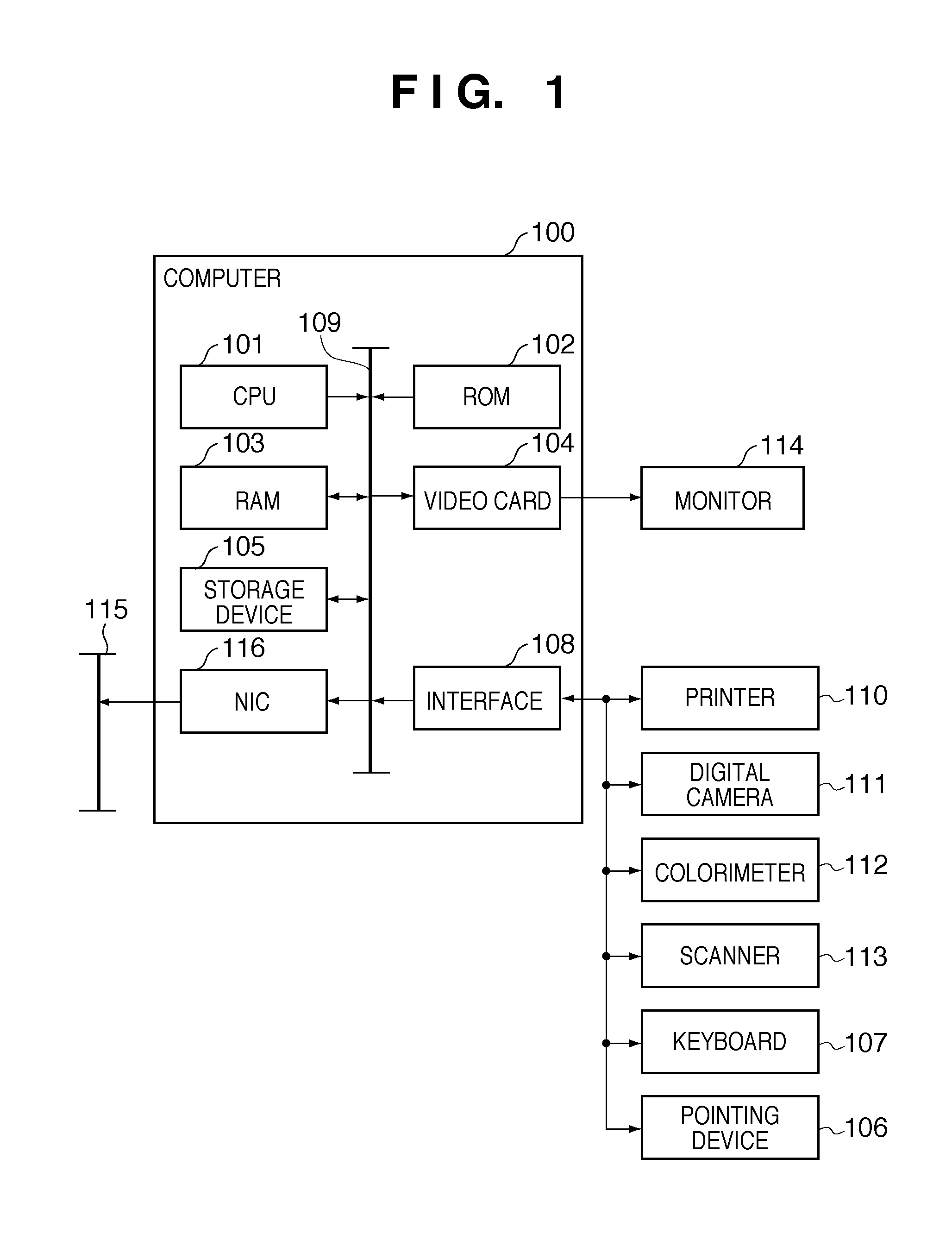
[0034]FIG. 1 is a diagram illustrating an example of a configuration of an image correction system. An information processing apparatus 100 includes a CPU 101, a ROM 102, a RAM 103, and a video card 104 that provides connection to a monitor 114 (which may include a touch panel). It further includes a storage device 105 serving as a storage area, such as an HDD (hard disk drive) or a memory card. The apparatus also includes an interface 108 for a serial bus such as USB or IEEE 1394 to provide connection to a pointing device 106 such as a mouse, a stylus, or a tablet and to a keyboard 107. The apparatus further includes a network interface card (NIC) 116 that provides connection to a network 115. These components are connected to one another via a system bus 109. The interface 108 can establish connection with a printer 110 such as an inkjet printer that serves as an image forming apparatus, a digital camera 111, a colorimeter 112, a scanner 113, and so on.

[0035]The CPU 101 loads a pr...

second embodiment

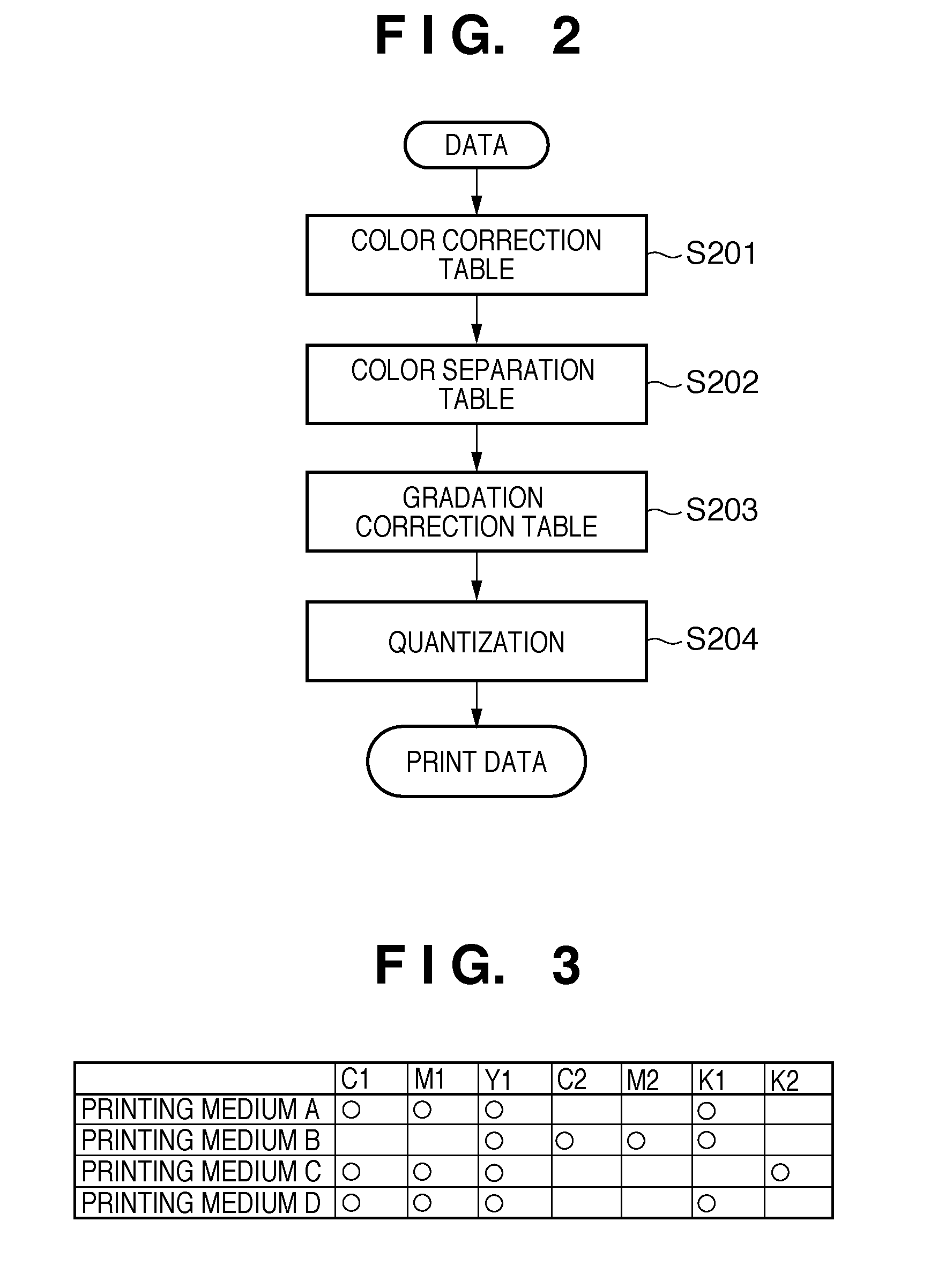
[0069]A second embodiment describes the case where the relationship between printing media and available inks are different from those described in the first embodiment. FIG. 12 illustrates the relationship between printing media and available inks according to the present embodiment. White circles in the figure represent the available inks for each printing medium. In the present embodiment, cyan ink (C1), magenta ink (M1), yellow ink (Y1), and black ink (K1) are used for both printing media, whereas red ink (R) and green ink (G) are used for only the printing medium E. The printing medium A is printed with C1, M1, Y1, and K1, and the printing medium E is printed with C1, M1, Y1, K1, R, and G. R ink and G ink have the feature that they are used neither on the gray axis nor in skin color areas and are used in only highly saturated red and green color areas.

[0070]Next, a combination of printing media A and E is described with reference to FIGS. 13 and 14. Although some of the inks, n...

third embodiment

[0072]The first and second embodiments have been described on the premise that calibration information on every chromatic color ink that satisfies the condition that available inks for each printing medium are always included in a history. However, calibration information that satisfies such a condition may not always be included in a history. Or the following case is also conceivable, i.e., even if included in a history, calibration information may have been acquired at a time that is older than a predetermined time and thus may not be usable in the production of a sufficient correction effect. An example of such a case is described.

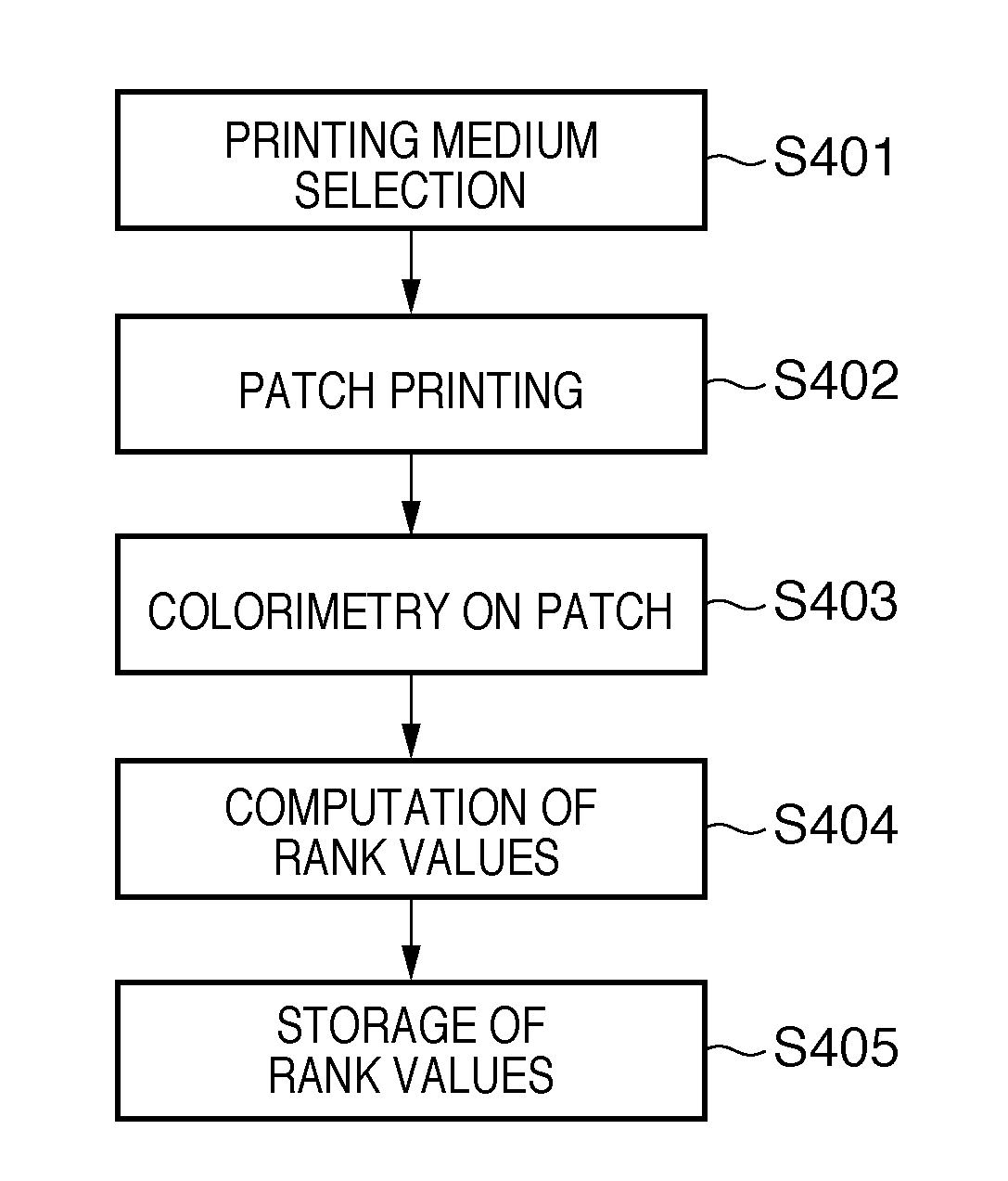
[0073]The calibration-information-acquiring step is as described in the first embodiment. Described below is a step of correcting and printing output using acquired calibration information. First, in step S501, a printing medium to be used for printing and the print quality thereof are specified by a user. Then, in step S502, the most up-to-date time wh...


PUM


Abstract

Every time density correction information corresponding to a colorimetric value of a patch is acquired, the time when the density correction information is acquired and the type of a printing medium on which the patch is printed are accumulated in association in a memory. The type of a medium for printing is specified by a user; density correction information acquired at the most up-to-date time for each chromatic color ink available for the medium of that type is read from the memory; it is determined whether or not the most up-to-date time when the density correction information is acquired for each of the chromatic color inks available for the specified medium is the same time; if the most up-to-date times are the same, density correction is performed on image data, using a correction table that corresponds to the density correction information acquired at the most up-to-date time.

Description

BACKGROUND OF THE INVENTION[0001]1. Field of the Invention[0002]The present invention relates to an image correction system and image correction method for correcting an image.[0003]2. Description of the Related Art[0004]Continuous use of the same printer results in variations in the output characteristics of the printer, such as output colors and gradation, due to changes in the density of ink, the ink discharge characteristics of the heads, or the like with the passage of time. A technique called “calibration” has been developed in order to stabilize the output characteristics irrespective of the above-mentioned changes with time. With the technique, the amounts of such output characteristics are measured at regular intervals, calibration information is computed from the measured values, and correction is performed based on the computed information, which enables a printer to be used with stable output characteristics. Since such calibration information is computed at regular inte...

Claims


Application Information

Patent Timeline
IPC IPC(8): B41J29/393
CPCH04N1/482B41J2/2103H04N1/6033B41J29/393
Inventor KAWAI, YOSHINORI
Owner CANON KK
Why Eureka
Try Eureka