
Apparatus and method for quantum cryptography communication

a quantum cryptography and apparatus technology, applied in the field of apparatus and methods for quantum cryptography communication, can solve the problems that the method cannot cope with a case, and the base axis of polarization used for quantum cryptography cannot be detected on the reception side between movable bodies that perform mobile communication, so as to achieve the effect of easy adjustment of the optical axis

Active Publication Date: 2010-08-19
NAT INST OF INFORMATION & COMM TECH
View PDF2 Cites 15 Cited by
  • Summary
  • Abstract
  • Description
  • Claims
  • Application Information

AI Technical Summary

Benefits of technology

[0016]It is an object of the present invention to provide a quantum cryptography communication apparatus that can adjust, even when relative positions between a transmitter and a receiver that perform quantum cryptography communication change, a base axis for polarization thereof between the transmitter and the receiver and synchronize signals.
[0017]It is another object of the present invention to provide a quantum cryptography communication method that can adjust, even when relative positions between a transmitter and a receiver that perform quantum cryptography communication change, a base axis for polarization thereof between the transmitter and the receiver and synchronize signals.
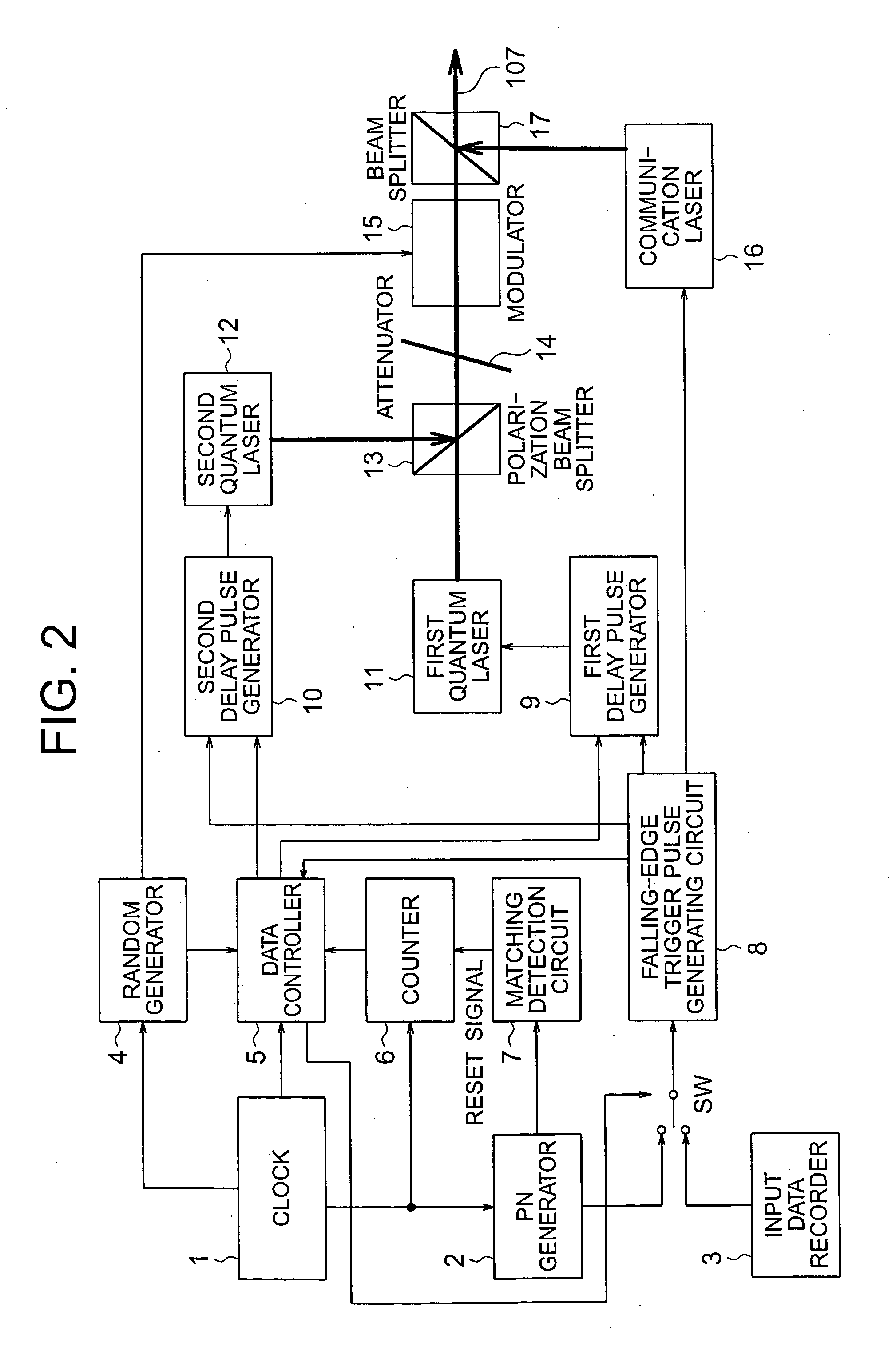
[0025]With the quantum cryptography communication apparatus according to the present invention, the quantum cryptography signal is transmitted and received in the period in which the communication signal is off in synchronization with a falling edge of the communication signal after elapse of a delay time set in advance from the falling edge. Consequently, it is possible to transmit and receive a relatively weak (actually, extremely weak) quantum cryptography signal without being disturbed by a communication signal including relatively strong pulse light.
[0026]With the quantum cryptography communication apparatus according to the present invention, a delay in relative time is detected by using the counters incremented according to transmission speed of the communication signal and reset at a cycle longer than a propagation delay of the communication signal. Consequently, when an arrival time of a photon is measured in quantum key distribution, it is possible to eliminate the necessity of having clocks, which accurately tick, in the transmission system and the reception system and eliminate the necessity of adjusting times of both the transmission system and the reception system to each other.
[0027]With the quantum cryptography communication apparatus according to the present invention, the communication signal and the quantum cryptography signal are transmitted and received on the same optical axis. Consequently, since only one optical axis has to be adjusted, it is possible to easily adjust the optical axis between the transmitter and the receiver.

Problems solved by technology

The method cannot cope with a case in which a clock signal is a data signal.
In addition to the above, according to the examination of the inventor, when it is attempted to apply the quantum cryptography communication to the mobile communication, a new problem occurs in that a base axis for polarization used for quantum cryptography cannot be detected on a reception side between movable bodies that perform the mobile communication.

Method used


Image

  • Apparatus and method for quantum cryptography communication
  • Apparatus and method for quantum cryptography communication
  • Apparatus and method for quantum cryptography communication

Examples


Embodiment Construction

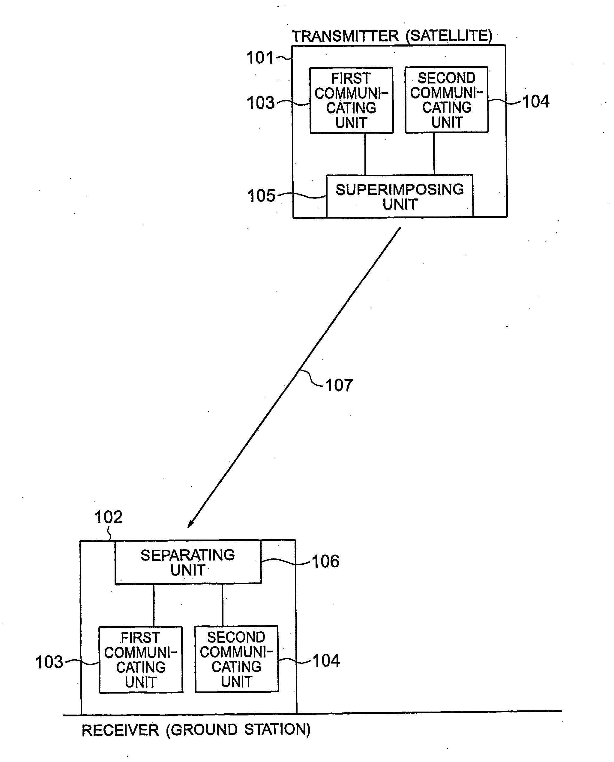
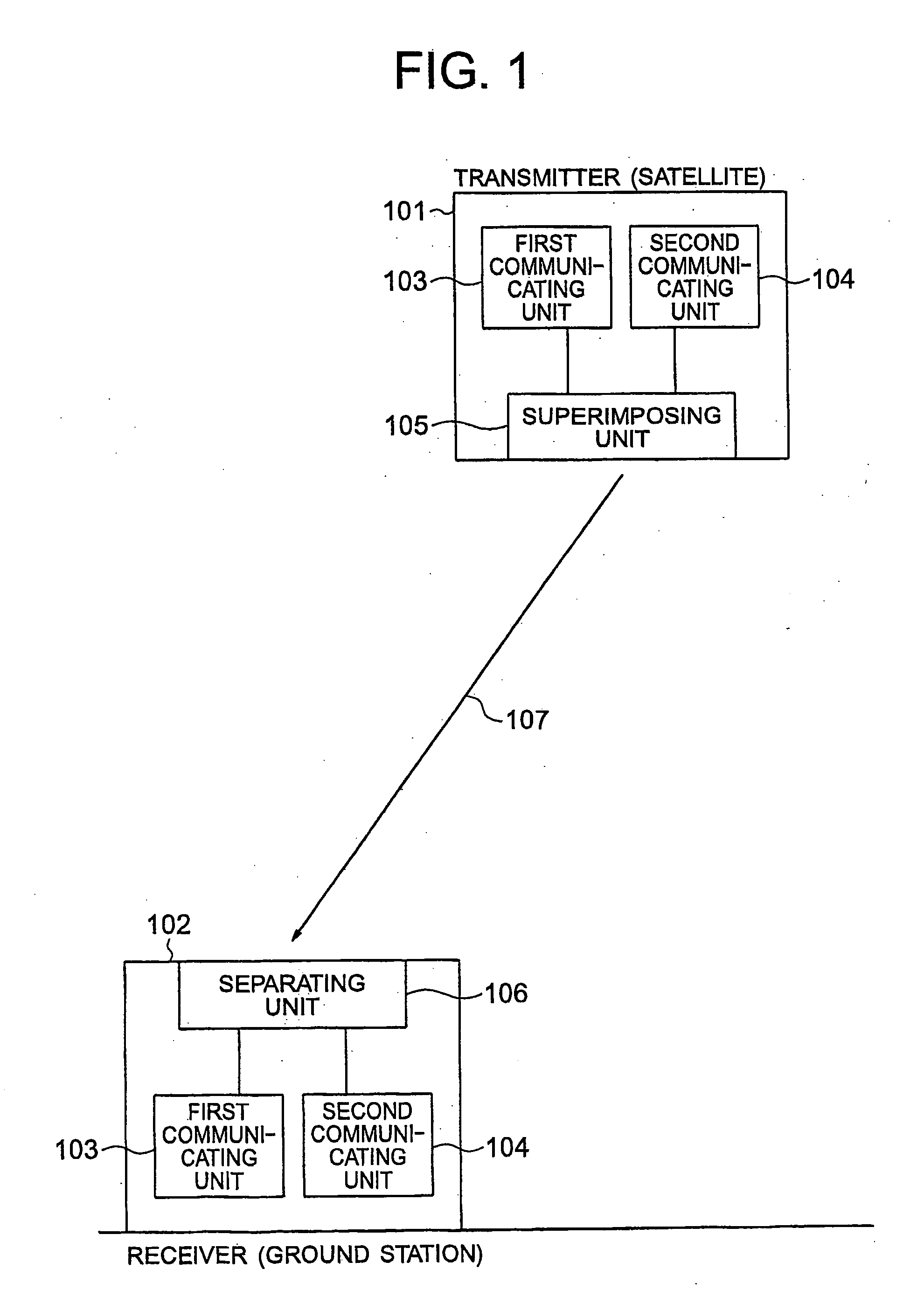
[0035]FIG. 1 is a diagram of a quantum cryptography communication apparatus according to the present invention and illustrates an example of a configuration of the quantum cryptography communication apparatus according to the present invention.

[0036]The quantum cryptography communication apparatus includes a transmitter 101 and a receiver 102 and performs quantum cryptography communication employing an optical signal (a laser beam) between the transmitter 101 and the receiver 102. The transmitter 101 includes, for example, a communication satellite 101. In other words, the transmitter 101 is a movable body. The receiver 102 includes, for example, a ground station (a base station) 102. In other words, the receiver 102 is a fixed station.

[0037]The quantum cryptography communication apparatus includes first communicating unit 103 and second communicating unit 104. The first communicating units 103 are provided in the transmitter 101 and the receiver 102, respectively, and transmit and ...


PUM


Abstract

A quantum cryptography communication apparatus performs quantum cryptography communication between a transmitter and a receiver. The quantum cryptography communication apparatus includes first communicating unit transmitting and receiving a communication signal including relatively strong pulse light between the transmitter and the receiver, and second communicating unit transmitting and receiving a relatively weak quantum cryptography signal between the transmitter and the receiver in a period in which the communication signal is off and the attitude axis for the receiver can be adjusted to that for the transmitter by the second communicating unit.

Description

BACKGROUND OF THE INVENTION[0001]1. Field of the Invention[0002]The present invention relates to an apparatus and method for quantum cryptography communication, and more particularly to an apparatus and method for quantum cryptography communication suitable when relative positions between a transmitter and a receiver that perform quantum cryptography communication such as mobile communication in satellites and the like change.[0003]2. Description of the Related Art[0004]In the quantum cryptography communication, a method of generating synchronization signals for loopback in a transmitter and a receiver and transmitting the synchronization signals is proposed for synchronization between the transmitter and the receiver (see Patent Document 1 and Patent Document 2).[0005]In the quantum cryptography communication, a method of exchanging synchronization pulses between QKD stations and locking a phase is proposed in order to surely perform detection of a weak quantum signal (see Patent D...

Claims


Application Information

Patent Timeline
Patent Type & Authority Applications(United States)
IPC IPC(8): H04L9/12H04L9/00
CPCH04L9/0858
Inventor TOYOSHIMA, MORIOFUJIWARA, MIKIOKUNIMORI, HIROO
Owner NAT INST OF INFORMATION & COMM TECH
Learn More