Optical transceiver module

Inactive Publication Date: 2010-08-19
HITACHI LTD
View PDF57 Cites 31 Cited by
  • Summary
  • Abstract
  • Description
  • Claims
  • Application Information

AI Technical Summary

Benefits of technology

[0010]According to the present invention, there is provided an optical module that remarkably reduces the number of parts and the number of mounting processes to reduce the

Problems solved by technology

This causes a drawback that is disadvantageous for a reduction in the size and costs.
However, this multiplexing device is configured so that the optical elements and the optical multiplexer and demultiplexer are coupled with each other th

Method used


Image

  • Optical transceiver module
  • Optical transceiver module
  • Optical transceiver module

Examples


Example

First Embodiment

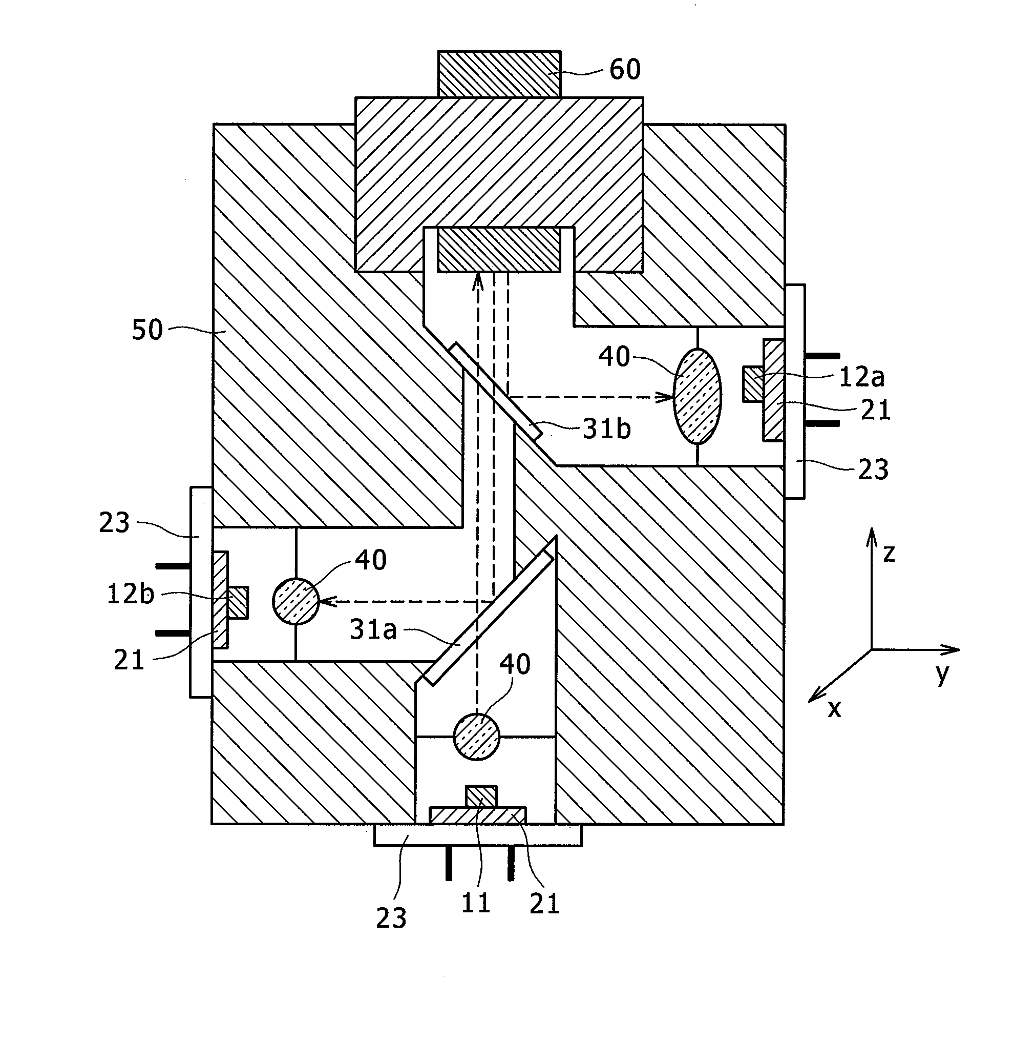
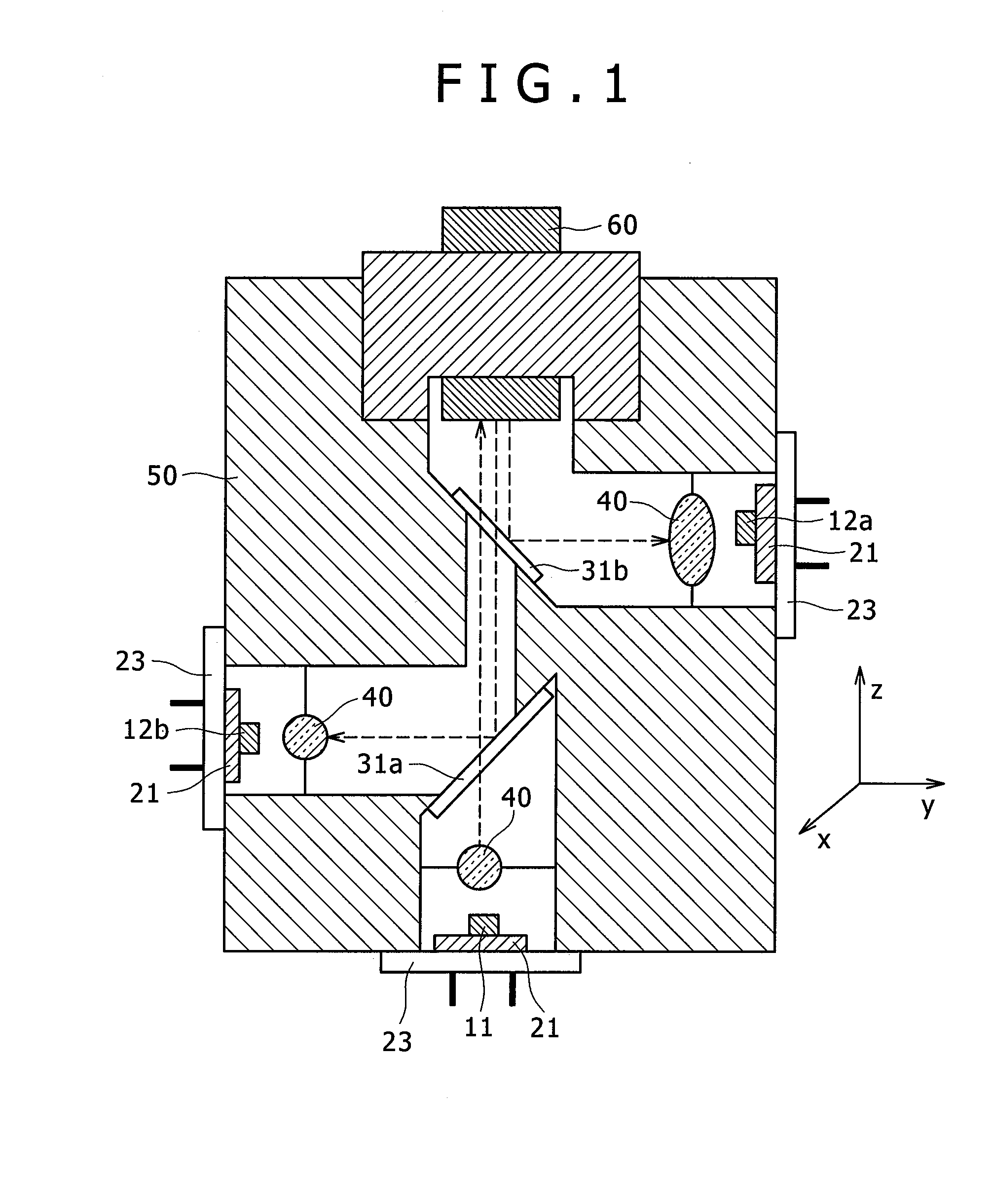
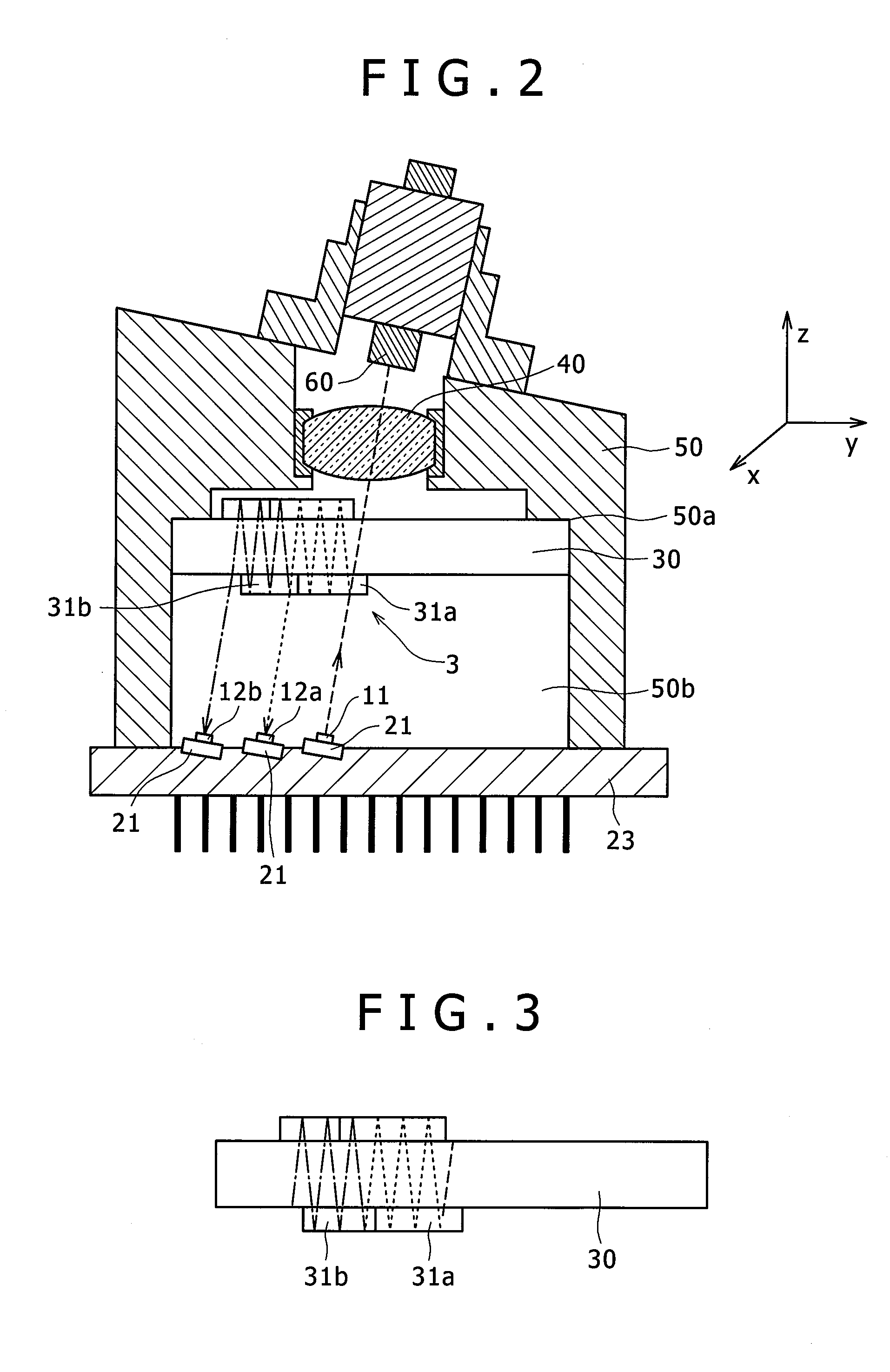
[0027]A first embodiment will be described with reference to FIG. 2. FIG. 2 is a cross-sectional view showing an example in which the present invention is applied to a three-wavelength bidirectional optical transceiver module having such a function that a light of a first wavelength output from the light emitting element is coupled to an optical fiber and transmitted therethrough, and a light of a second wavelength and a light of a third wavelength are separated in wavelength from a light multiplexed in wavelength and output from the optical fiber, and guided to and received by corresponding light receiving elements, respectively.

[0028]A package (housing) 50 has a lens 40 and an optical multiplexer and demultiplexer 3 therein, and is attached with a base 23 having a light emitting element 11 and light receiving elements 12. Also, the package 50 is attached to an optical fiber 60.

[0029]The light emitting element 11 and light receiving elements 12a, 12b are adhered to ...

Example

Second Embodiment

[0039]FIGS. 5 to 10 are diagrams for explaining a second embodiment. FIG. 5 is a diagram enlarging a portion where the light emitting element 11 is mounted on the base 23 in the optical transceiver module having a hemispherical recess formed in a portion on which the light emitting element and the light receiving element are mounted, in the first embodiment.

[0040]A procedure of adjusting the outgoing direction is shown in FIGS. 6A to 6E.

[0041]First, as shown in FIG. 6A, an FFP (far field pattern) of the light emitting element 11 that is mounted on the substrate 21 by soldering is measured by an FFP measuring unit 80 to specify an outgoing direction (θ0, θ0).

[0042]Subsequently, as shown in FIG. 6B, the substrate 21 is adhered to the hemispherical pedestal 22 by Ag paste or soldering.

[0043]Then, the substrate 21 is grasped by a manipulator 90 having stages 94 and 95 movable in directions θ and φ, and stages 91, 92, and 93 movable in directions X, Y, and Z. The substra...


PUM


Abstract

There are provided a downsized and low-cost optical module used as a terminal for wavelength multiplexing optical transmission and one-core bidirectional optical transmission which transmits lights of plural wavelengths through one optical fiber, and a method of manufacturing the optical module. A base on which plural optical elements are mounted, and an optical multiplexer and demultiplexer having wavelength selection filters and mirrors formed on both surfaces of a substrate are prepared. Those two parts are packed into a package so that an optical element mounted surface and a filter surface are substantially parallel to each other, and the optical elements are arranged to emit or receive lights obliquely to the base. With this configuration, because the optical multiplexer and demultiplexer can be mounted in parallel to an X-Y plane, a package can be easily machined by using a lathe, thereby enabling a reduction in the costs.

Description

BACKGROUND OF THE INVENTION[0001](1) Field of the Invention[0002]The present invention relates to an optical module, and more particularly to a multiwavelength optical transmitter module that multiplexes and transmits lights of plural wavelengths, and a multiwavelength optical receiver module that demultiplexes and receives a light obtained by multiplexing the plural wavelengths.[0003](2) Description of the Related Art[0004]In the recent information communication field, a communication traffic that reciprocates large volumes of data at a high speed by the aid of lights is rapidly improved. In particular, broadbandization of an access line associated with an explosive spread of the Internet is accelerated, and the remarkable rising of an FTTH (fiber to the home) service on the market has been found. Among the optical transmission systems of the FTTH, a PON (passive optical network) system in which plural subscribers share one optical fiber is now growing in demand. In that system, da...

Claims


Application Information

Patent Timeline
IPC IPC(8): H04J14/00H04B10/00G02B6/42
CPCG02B6/4201G02B6/4214H04B10/40G02B6/423G02B6/4246G02B6/4215G02B6/424G02B6/4244G02B6/4245G02B6/4253G02B6/4257G02B6/4259
Inventor SAKIGAWA, YUKIOTAKAI, TOSHIAKIHATA, SHOHEI
Owner HITACHI LTD
Why Eureka
Try Eureka