System and method for managing and maintaining abrasive blasting machines

a technology of abrasive blasting machine and a management system, which is applied in the direction of process and machine control, computer control, instruments, etc., can solve the problems of increasing the cost of replacement of structures, and increasing the cost of maintenance and repair of structures, so as to improve the efficiency of the industry and reduce the downtime of machines

Active Publication Date: 2010-08-19
ROTO GRIT LLC
View PDF90 Cites 32 Cited by
  • Summary
  • Abstract
  • Description
  • Claims
  • Application Information

AI Technical Summary

Benefits of technology

[0010]To overcome the problems and shortcomings of the abrasive blasting industry that has existed for many years, intelligence may be added to abrasive blasting equipment. Intelligence may be added to abrasive blasting equipment through the use of sensors and computers and provide for monitoring, collecting, processing, and presenting operational data produced by an abrasive blasting equipment. Such data may enable owners/operators and end customers to have significantly more inform

Problems solved by technology

While these materials are strong and relatively inexpensive, corrosion and weathering results in a need to maintain, repair, or replace the structures.
Replacement of structures is expensive and oftentimes inconvenient to the public.
Industrial abrasive blasting processes, invented in the early 1900s, for use in preparing surfaces for protective coatings have always been relatively expensive based on a need for large volumes of high pressure compressed air at up to 200 psi.
Because the abrasive blasting process, whether fixed or mobile, requires large amounts of complex blasting equipment and manpower to operate and manage the equipment, the hourly cost of fixed or mobile work is substantial.
In addition to the cost of steel and other materials increasing, labor costs have also increased.
Operational data has been primarily empirically collected after the fact using a macroscopic view (e.g., approximately two days to complete a 450 square foot section of a steel bridge structure), and detailed operational data that would provide an owner with more in

Method used


Image

  • System and method for managing and maintaining abrasive blasting machines
  • System and method for managing and maintaining abrasive blasting machines
  • System and method for managing and maintaining abrasive blasting machines

Examples


Embodiment Construction

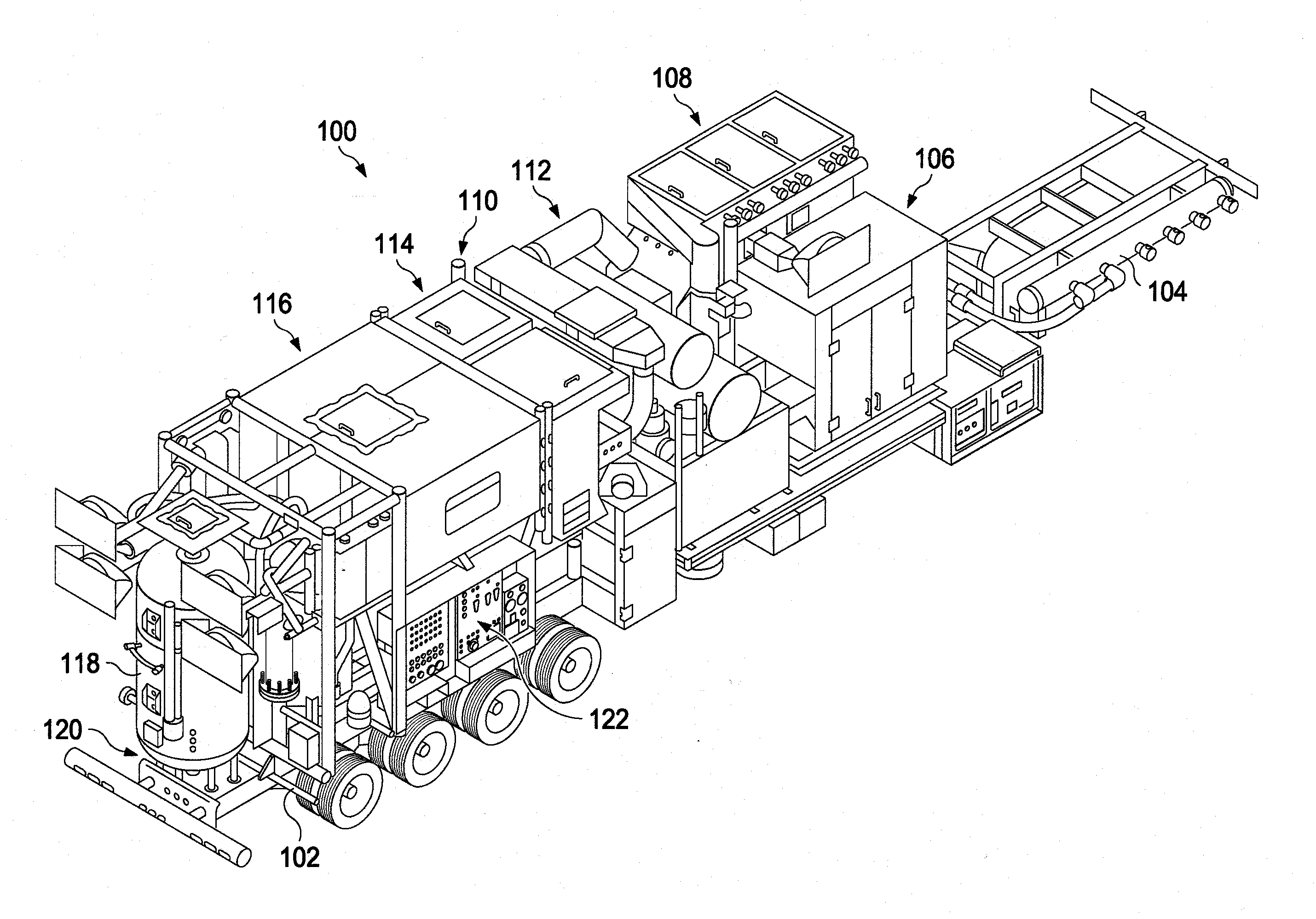
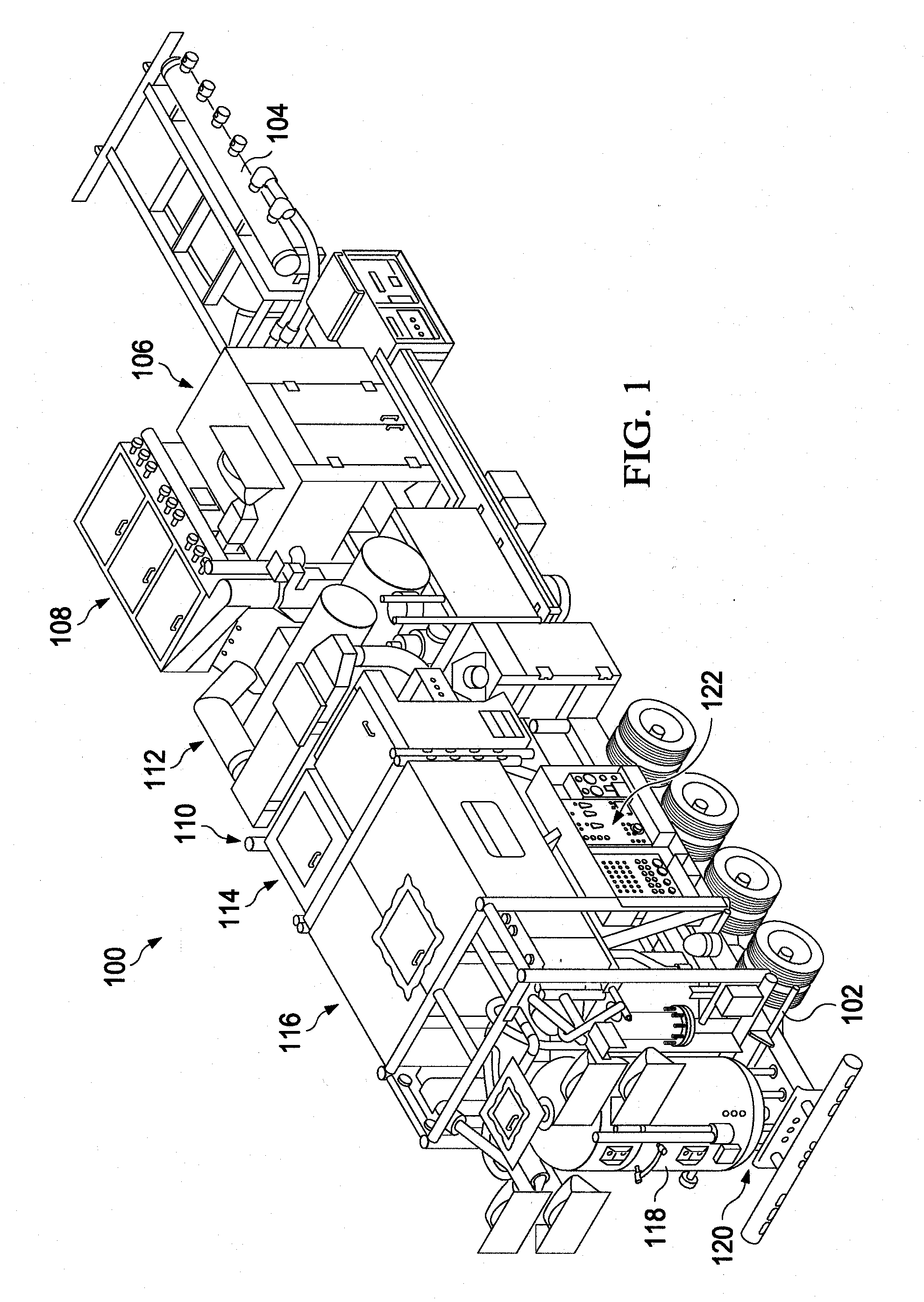
[0036]With regard to FIG. 1, an illustration of an illustrative abrasive blasting machine 100 is shown. The abrasive blasting machine 100 in this configuration is mobile in that it resides on a trailer 102 that enables the abrasive blasting machine 100 to be transported from job site to job site for performing abrasive blasting on a structure (e.g., bridge) at the job site. From front to rear, the abrasive blasting machine 100 includes a compressor manifold 104 that enables multiple compressors to feed into the manifold 104 for use in blowing blast media by the abrasive blasting machine 100. An engine 106, which may be a diesel engine or other powered engine, for use in producing vacuum power and generating hydraulic power for driving various components on the abrasive blasting machine 100. A vacuum 108 may be utilized to enable an operator of the abrasive blasting machine 100 to vacuum blast media after the blast media is projected onto surfaces of a structure being prepared for a ...


PUM

PropertyMeasurementUnit
Timeaaaaaaaaaa
Ratioaaaaaaaaaa

Abstract

A system and method for managing abrasive blasting may include timing duration of blast media being blown in performing abrasive blasting using an abrasive blasting machine. Time duration that an operator worked in association with the duration of the blast media being blown may be received. A blasting efficiency ratio may be computed based on the duration of the blasting media being blown and duration of that the operator worked. The blasting efficiency ratio may be displayed to a user.

Description

RELATED APPLICATIONS[0001]This U.S. patent application is related to co-pending U.S. Patent Application Ser. No. 61 / 153,193 filed on Feb. 17, 2009, the entire contents of which are herein incorporated by reference in their entirety.BACKGROUND[0002]Large structures, such as bridges, tunnels, tanks, ships, and so forth, are generally formed of concrete and steel. While these materials are strong and relatively inexpensive, corrosion and weathering results in a need to maintain, repair, or replace the structures. Replacement of structures is expensive and oftentimes inconvenient to the public. One technique for maintaining or repairing structures includes the use of abrasive blasting to clean or strip surfaces of the structure.[0003]Abrasive blasting uses a variety of blast media, including sand, coal slag, garnet, steel grit, and other blast media, and is the most common method of removing corrosion and coatings from steel and concrete surfaces. In its simplest form, blast media under...

Claims


Application Information

Patent Timeline
IPC IPC(8): G06Q10/00B24C1/00G06F17/00G07C1/10
CPCB24C9/00G07C1/10G06Q50/08G06Q10/20B24C7/00G05B15/02
Inventor BENSON, RONALD C.
Owner ROTO GRIT LLC
Why Eureka
Try Eureka