Holographic Reconstruction System with an Optical Wave Tracking Means

Inactive Publication Date: 2010-08-26
SEEREAL TECHNOLOGIES
View PDF1 Cites 43 Cited by
  • Summary
  • Abstract
  • Description
  • Claims
  • Application Information

AI Technical Summary

Benefits of technology

[0022]The object of the present invention is to provide a holographic reconstruction system with a wave tracking means for a propagating wave field while doing without a switchable modulator cell array or switchable light source array with discretely controllable point light sources for directing the wave field, and thereby sidestepping its low luminous efficiency. Both the number of optical components through which the light passes and the demands made on the optical components of the system shall be minimised, so that the structure of the modulated light waves remains widely constant irrespective of the current eye position of an observ

Problems solved by technology

When using a light modulator which was designed for conventional image representation in holography, it is disadvantageous that the light modulator exhibits a diffraction angle which is rather small for holography, due to a typical distance of approx.
This makes it impossible for a reconstruction to be watched simultaneously with both eyes through a single visibility region.
This makes great demands on the working speed of the light modulator means.
It is disadvantageous that in a large tracking range, substantial aberrations, which occur when light passes through the focussing means, adversely affect the reconstruction of the spatial scene.
Because the object light points are reconstructed by wave interferences of diffracted partial light waves, such aberrations can cause image errors of a type not known from conventional video image representations as a result of phase and runtime errors.
For example, other partial light waves than intended when computing the hologram according to the holographic source signal can interfere and generate misplaced object light points or additional object light points compared with the original scene.
It is extremely complicated to provide such a li

Method used


Image

  • Holographic Reconstruction System with an Optical Wave Tracking Means
  • Holographic Reconstruction System with an Optical Wave Tracking Means
  • Holographic Reconstruction System with an Optical Wave Tracking Means

Examples


Embodiment Construction

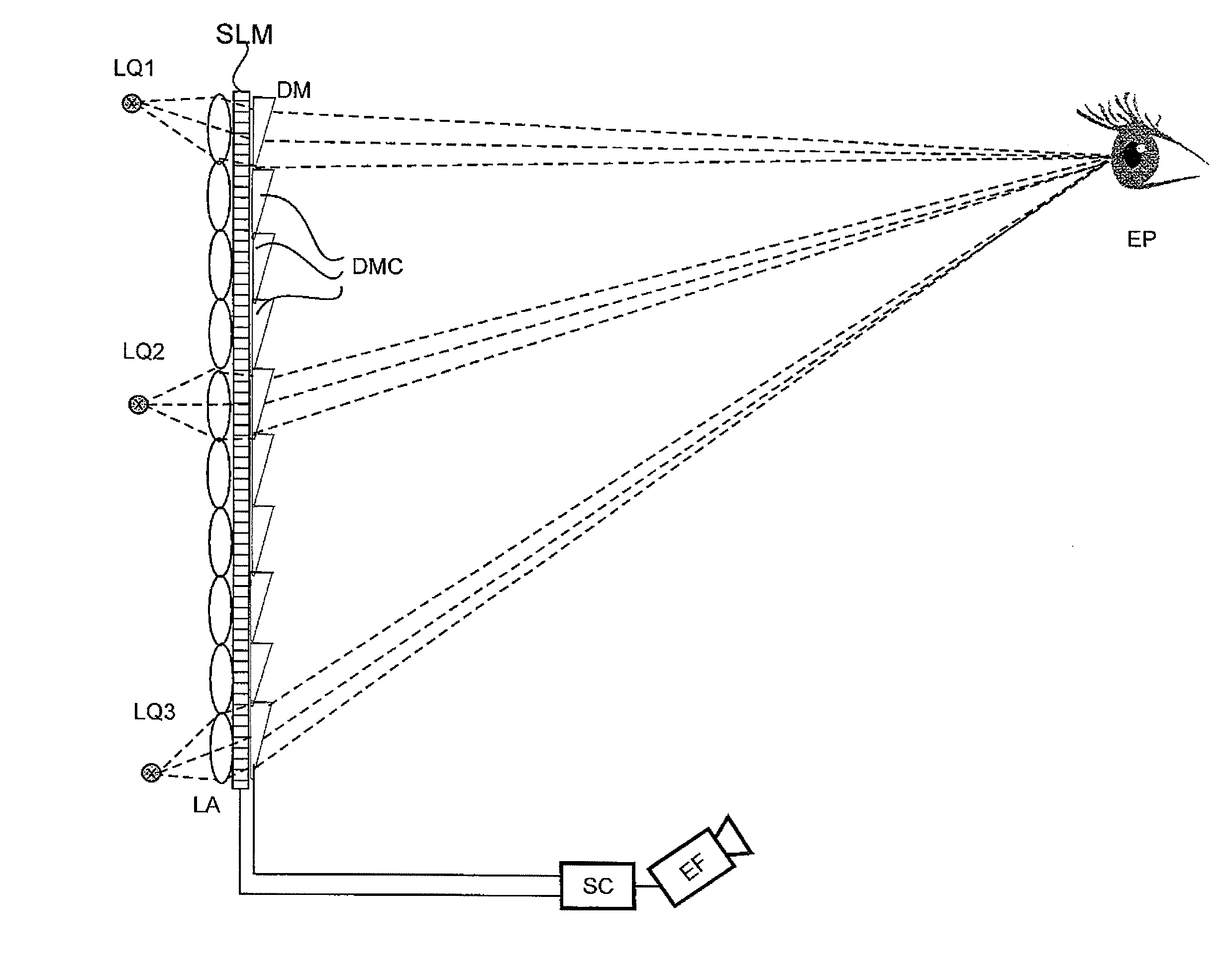
[0058]In the following embodiments, an electronic system controller SC encodes sequences of video holograms directly on a large-area flat screen of a type known from video and TV technology, such as an LCD panel, which directly serves an observer as a display screen, and which has a surface area which is as large as possible so to achieve a large viewing angle when watching the reconstruction.

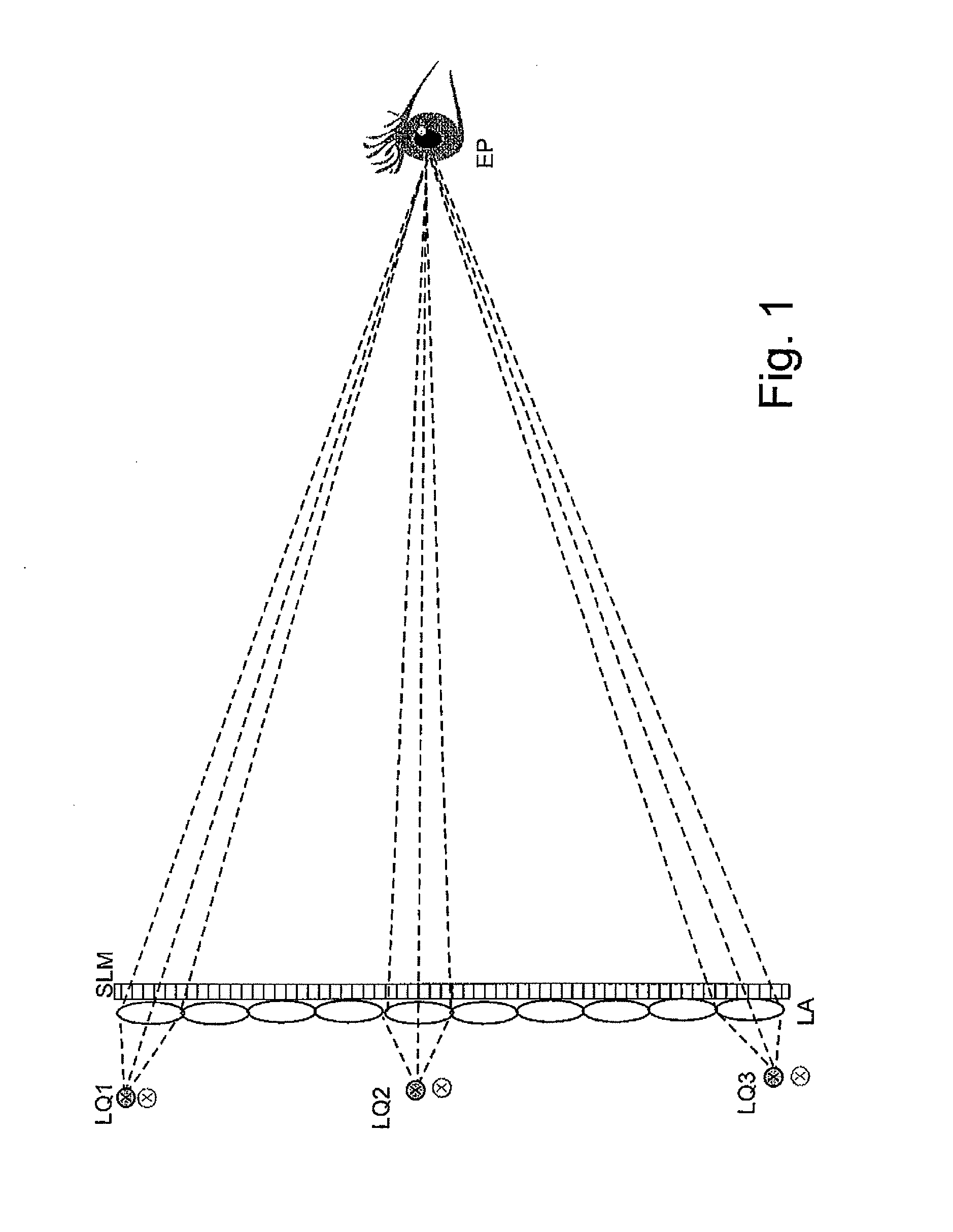
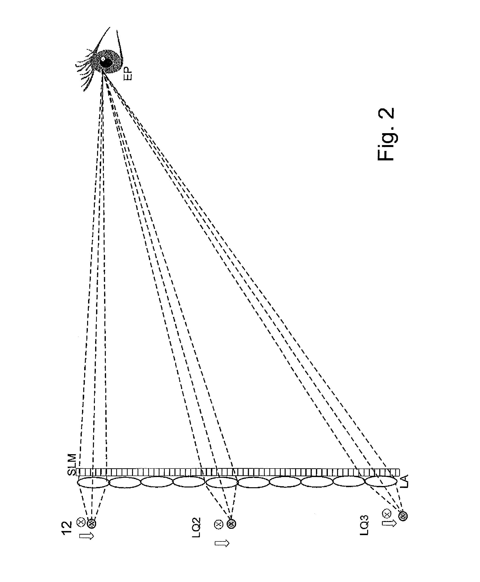
[0059]FIG. 1 shows a holographic reconstruction system according to the initial prior art solution with selected point light sources LQ1, LQ2 and LQ3, which emit light which is capable of generating interference, and which are part of an array of light sources. The array of light sources comprises for each imaging element of an array of focussing means LA a corresponding point light source LQ1, LQ2 or LQ3, which emit light which is capable of generating interference. Each imaging element of the array of focussing means LA forms together with a corresponding light source an illumination unit for...


PUM


Abstract

A holographic reconstruction system is disclosed with spatial light modulation means, modulating interferable light waves from light sources with at least one video hologram, comprising optical focusing means, focusing the modulated light waves with the reconstructed object light points for at least one eye position for the eyes of observers and controllable electro-optical deflector means, which direct the focused modulated light waves with the reconstructed light points to at least one eye position in order to reduce the aberrations. The reconstruction system has the optical focusing means in a field of focusing elements, wherein each focusing element is provided with at least one interferable light source. The electro-optical deflector means lie in the light path of the interferable light waves after the optical focusing mean and have at least one field of deflector elements, which has at least one separately controllable electro-optical deflector element for each focusing element.

Description

FIELD OF THE INVENTION[0001]The present invention relates to a holographic reconstruction system for the three-dimensional reconstruction of a scene with spatial light modulator means, which carry a holographic code, and with illumination means for illuminating the light modulator means.[0002]The present invention chiefly relates to a real-time or near-real-time reconstruction of moving scenes with the help of a sequence of video holograms. A hologram processor computes video holograms and encodes them on a cell structure of spatial light modulator means which, when illuminated with light which is capable of generating interference, spatially modulate at least one propagating light wave field with holographic information. The modulated light wave field reconstructs the scene through interference of the diffracted light waves and thus propagates towards an eye position such that one or multiple observers can watch the reconstructed object light points as a three-dimensional reconstru...

Claims


Application Information

Patent Timeline
IPC IPC(8): G03H1/22
CPCG02B5/045G02B5/06G02B26/005G03H1/02G03H2225/55G03H1/2294G03H2001/0216G03H2223/18G03H2223/19G03H1/2205G02B26/00G03H1/04
Inventor KROLL, BOSCHWERDTNER, ARMINFUTTERER, GERALDREICHELT, STEPHANLEISTER, NORBERT
Owner SEEREAL TECHNOLOGIES
Why Eureka
Try Eureka