Cylindrical grinder and cylindrical grinding method of ingot

a cylindrical grinder and cylindrical technology, applied in the direction of grinding drives, other manufacturing equipment/tools, manufacturing tools, etc., can solve the problems of deteriorating productivity, requiring a lot of manpower for the centering (or correction of the centering), and deteriorating process precision, so as to improve process precision and facilitate centering.

Active Publication Date: 2010-08-26
SUMCO CORP
View PDF21 Cites 9 Cited by
  • Summary
  • Abstract
  • Description
  • Claims
  • Application Information

AI Technical Summary

Benefits of technology

[0034]In this instance, the top portion side of the ingot is placed at a lower position, and the tail portion side is placed at an upper position, so that the ingot is clampingly held. It is possible to clampingly hold the ingot by applying the strong compressive force to the top portion side due to the weight of the ingot itself and applying the weak clamping force on the tail portion side. Therefore, in the case in which generation of dislocation occurs at the tail portion of the ingot, it is possible to clampingly hold the ingot appropriately by reliably preventing the tail portion side from being damaged without applying the strong compressive force, which is generated due to the weight of the ingot itself, on the tail portion side which is vulnerable to the compressive force. As a result, it is possible to perform the cylindrical grinding without cutting the dislocation occurring portion of the tail portion prior to t

Problems solved by technology

Since the cylindrical grinder A of the related art is adapted to clampingly hold the ingot 1 by using the support unit 2 (i.e., the pair of left and right support devices 4 and 5) in the state in which the direction of axis line O1 is disposed along the transverse direction T1, as shown in FIG. 19, there is a problem in that when the enlarged and weighted ingot 1 is cylindrically ground, deformation occurs in the ingot 1, and thus process precision is deteriorated.
Therefore, in the cylindrical grinder A of the related art which clamping

Method used


Image

  • Cylindrical grinder and cylindrical grinding method of ingot
  • Cylindrical grinder and cylindrical grinding method of ingot
  • Cylindrical grinder and cylindrical grinding method of ingot

Examples


Embodiment Construction

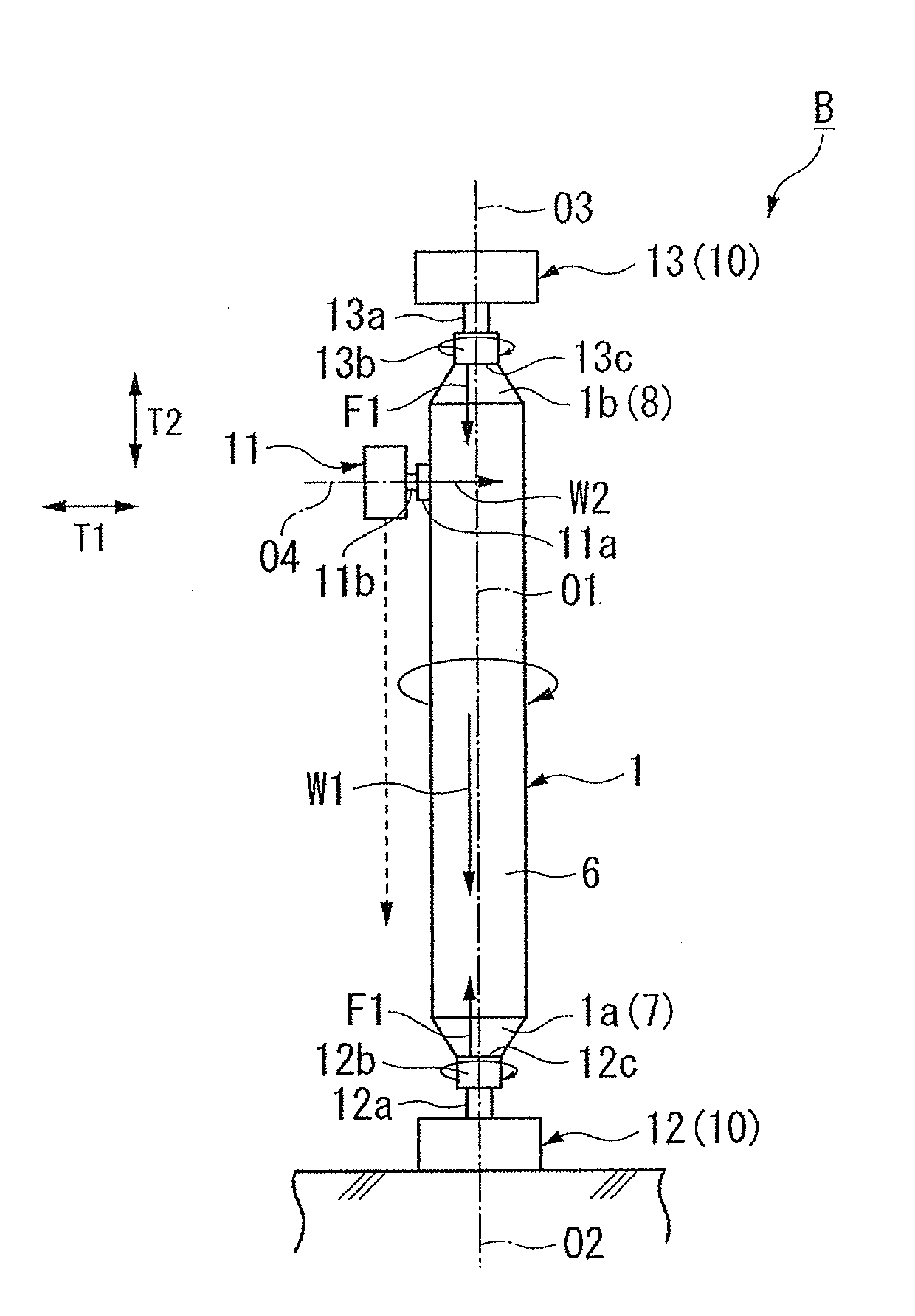
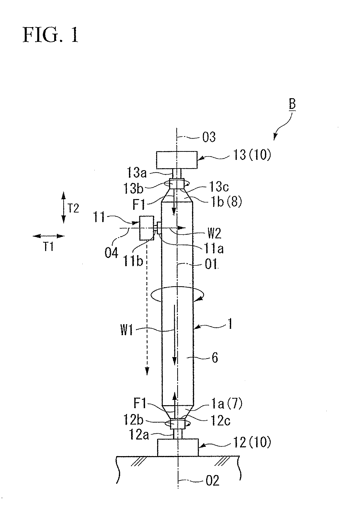
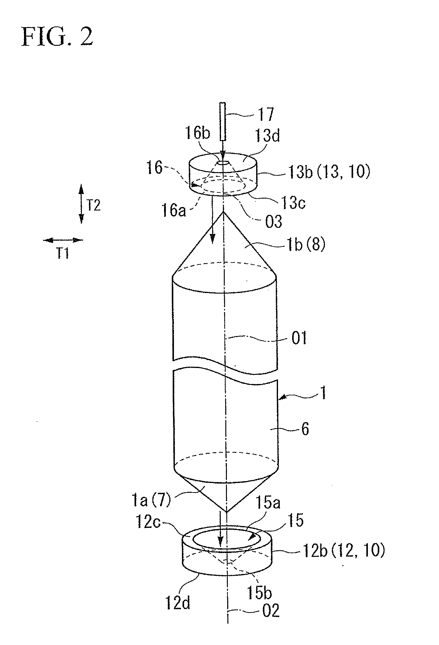
[0052]A cylindrical grinder and a cylindrical grinding method of an ingot according to an embodiment of the invention will now be described with reference to FIGS. 1 to 8. The embodiment relates to a cylindrical grinder and a cylindrical grinding method of an ingot used when an outer circumference of the ingot of silicon single crystal manufactured by a Czochralski method is subjected to traverse grinding.

[0053]A cylindrical grinder B of this embodiment includes, as shown in FIG. 1, a support unit 10 clamping an ingot 1 in a direction of axis line O1 and clampingly holding the ingot to rotate the ingot around the axis line O1, and a grinding unit 11 for traverse grinding the outer circumference of the ingot 1 while moving in the direction of axis line O1 of the ingot 1.

[0054]The support unit 10 includes a pair of a lower support device 12 and an upper support device 13 which clampingly hold both end portions 1a and 1b sides of the ingot 1 in the direction of axis line O1. The lower ...


PUM

PropertyMeasurementUnit
Diameteraaaaaaaaaa

Abstract

A cylindrical grinder is disclosed that includes a support unit including an upper support device and a lower support device, in which an ingot of silicon single crystal is interposed in a direction of axis line between the upper support device and the lower support device and is clampingly held to be rotated around the axis line, and a grinding unit that relatively moves along the direction of axis line of the ingot to traverse grind an outer circumference of the ingot. The upper support device is placed at an upper position and the lower support device is placed at a lower position, so that the support unit clampingly holds the ingot in a state in which the direction of the axis line of the ingot is disposed along a vertical direction.

Description

BACKGROUND OF THE INVENTION[0001]1. Field of the Invention[0002]The present invention relates to a cylindrical grinder and a cylindrical grinding method which can perform traverse grinding on an outer circumference of an ingot of silicon single crystal.[0003]Priority is claimed on Japanese Patent Application No. 2009-042888, filed Feb. 25, 2009, the contents of which are incorporated herein by reference.[0004]2. Description of Related Art[0005]Previously, a wafer used in a semiconductor device has been manufactured by producing an ingot of silicon single crystal (crystal rod) by a Czochralski method (CZ method), traverse grinding an outer circumference of the ingot by a cylindrical grinder to finish the ingot to have a predetermined dimension (diameter), and slicing the ingot in a direction perpendicular to an axis line of the ingot.[0006]For example, FIG. 18 shows one example of a cylindrical grinder A of a related art which traverse grinds the outer circumference of an ingot 1. Th...

Claims


Application Information

Patent Timeline
IPC IPC(8): B24B5/04B24B5/36B24B41/06
CPCB24B5/047B24B5/50B24B5/045B24B41/061
Inventor KAITO, RYOICHI
Owner SUMCO CORP
Why Eureka
Try Eureka