Premixed direct injection disk

a technology of direct injection and combustion system, which is applied in the direction of combustion types, machines/engines, lighting and heating apparatus, etc., can solve the problems of low emission combustors, high flame speed of certain fuels such as hydrogen or syngas, and the design of premixed hydrogen fuel combustion system is challenged

Active Publication Date: 2010-09-02
GENERAL ELECTRIC CO
View PDF17 Cites 120 Cited by
  • Summary
  • Abstract
  • Description
  • Claims
  • Application Information

AI Technical Summary

Benefits of technology

[0006]The present invention is a premixed direct injection disk design that provides good fuel air mixing with low combustion generated NOx and low flow pressure loss translating to a high gas turbine efficiency. The premixed direct injection disk is designed to replace fuel nozzles and cap assembly that are commonly found at the held end of a can-style combustor. The invention is durable, easy to construct, and has low risk of flash back of the flame into the nozzle.

Problems solved by technology

There are several problems associated with dry low emissions combustors operating with lean premixing of fuel and air.
However, certain fuels such as hydrogen or syngas have a high flame speed.
Due to the high turbulent flame velocity and wide flammability range, premixed hydrogen fuel combustion system design is challenged by flame holding and flashback at reasonable nozzle pressure loss.
However, with more reactive fuels, such as high hydrogen fuel, designing for flame holding margin and target pressure drop becomes a challenge.
Since the design point of state-of-the-art nozzles may approach 3000 degrees Fahrenheit bulk flame temperature, flashback into the nozzle leading to a held flame could cause extensive damage to the nozzle in a very short period of time.

Method used


Image

  • Premixed direct injection disk
  • Premixed direct injection disk
  • Premixed direct injection disk

Examples


Embodiment Construction

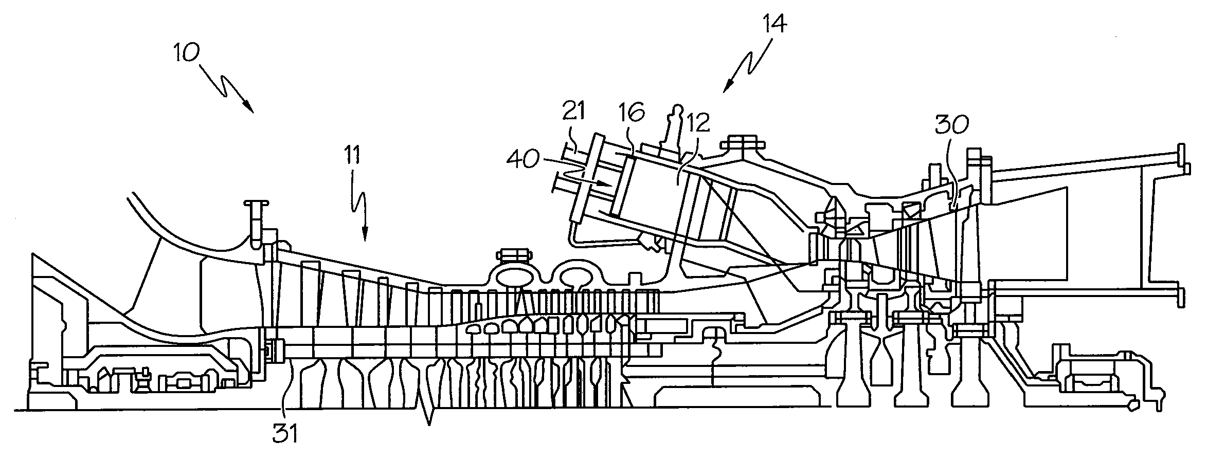
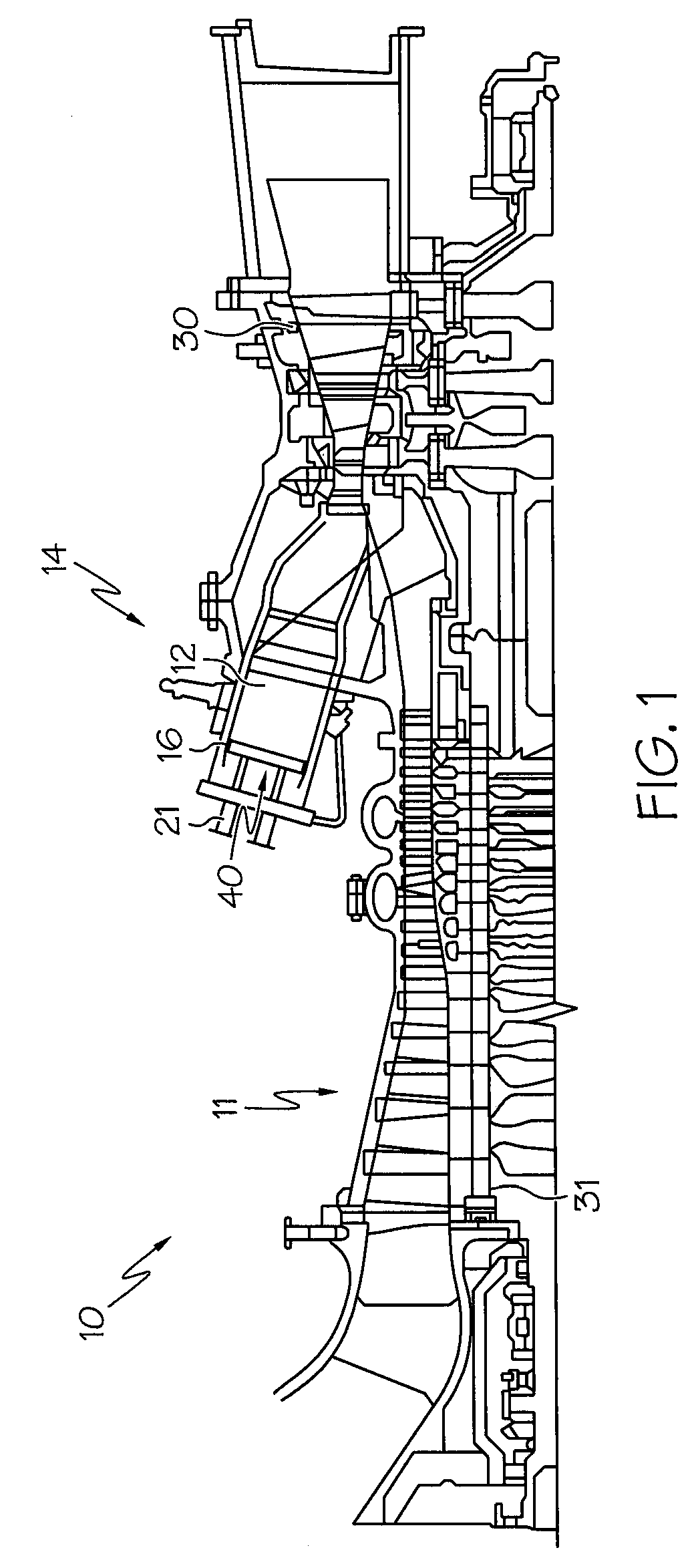
[0020]Referring now to FIG. 1 where the invention will be described with reference to specific embodiments, without limiting same, a schematic illustration of an exemplary gas turbine engine 10 is shown. Engine 10 includes a compressor 11 and a combustor assembly 14. Combustor assembly 14 includes a combustor assembly wall 16 that at least partially defines a combustion chamber 12. A pre-mixing injection disk 40 extends across at least a portion of the combustor assembly 14 and leads into combustion chamber 12. As will be discussed more fully below, disk 40 receives a first fluid or fuel through a fuel inlet 21 and a second fluid or compressed air from compressor 11. The fuel and compressed air are then mixed, passed into combustion chamber 12 and ignited to form a high temperature, high pressure combustion product or gas stream. Although only a single combustor assembly 14 is shown in the exemplary embodiment, engine 10 may include a plurality of combustor assemblies 14. In any eve...


PUM


Abstract

A fuel / air mixing disk for use in a fuel / air mixing combustor assembly is provided. The disk includes a first face, a second face, and at least one fuel plenum disposed therebetween. A plurality of fuel / air mixing tubes extend through the pre-mixing disk, each mixing tube including an outer tube wall extending axially along a tube axis and in fluid communication with the at least one fuel plenum. At least a portion of the plurality of fuel / air mixing tubes further includes at least one fuel injection hole have a fuel injection hole diameter extending through said outer tube wall, the fuel injection hole having an injection angle relative to the tube axis. The invention provides good fuel air mixing with low combustion generated NOx and low flow pressure loss translating to a high gas turbine efficiency, that is durable, and resistant to flame holding and flash back.

Description

FEDERAL RESEARCH STATEMENT[0001]This invention was made with Government support under Contract No. DE-FC26-05NT42643, awarded by the Department of Energy. The Government has certain rights in the invention.BACKGROUND OF THE INVENTION[0002]The subject matter disclosed herein relates to premixed direct injection combustion system and more particularly to a direct injection disk having good mixing, flame holding and flash back resistance.[0003]The primary air polluting emissions usually produced by gas turbines burning conventional hydrocarbon fuels are oxides of nitrogen, carbon monoxide, and unburned hydrocarbons. It is well known in the art that oxidation of molecular nitrogen in air breathing engines is highly dependent upon the maximum hot gas temperature in the combustion system reaction zone. One method of controlling the temperature of the reaction zone of a heat engine combustor below the level at which thermal NOx is formed is to premix fuel and air to a lean mixture prior to...

Claims


Application Information

Patent Timeline
Patent Type & Authority Applications(United States)
IPC IPC(8): F02C7/22
CPCF23R3/286F23R2900/03282F23D2209/10F23D14/82F23D14/02
Inventor YORK, WILLIAM DAVIDZIMINSKY, WILLY STEVEJOHNSON, THOMAS EDWARDLACY, BENJAMINZUO, BAIFANGUHM, JONG HO
Owner GENERAL ELECTRIC CO
Why Eureka
Try Eureka