
Concentrated solar system

Inactive Publication Date: 2010-09-02
QUADRA SOLAR CORP
View PDF7 Cites 39 Cited by
  • Summary
  • Abstract
  • Description
  • Claims
  • Application Information

AI Technical Summary

Benefits of technology

[0009]Lowest cost per solar watt coupled with low maintenance and long life.
[0021]The collector subsystem is less expensive than standard lenses or parabolic dish collectors. Most system components will be fabricated from low-cost materials and using conventional manufacturing processes. The system is estimated to be highly durable and have low operation and maintenance costs. Unlike standard panels made fully of expensive silicone, the system minimizes silicon consumption by utilizing small-size concentrated photovoltaic cells.
[0023]The modular arrangement allows arrays to be installed quickly and in any required configuration or size. The system is highly scalable making it possible to deploy from one to hundreds of sub-arrays.
[0025]An elevated version of one embodiment of the present invention is erected at a sufficient height above ground will allow for the full use of the land beneath for agricultural and other purposes, which minimizes the overall footprint. A well spaced out collector-bearing pipes, permits the vast majority of the sunrays to reach the ground below. This translates into a considerable reduction of any environmental land impact of the system when compared to using standard solar panels.

Problems solved by technology

Conversion from sunlight to electricity is direct, so that bulky mechanical generating systems are unnecessary.
However, to make it possible, more complicated reflecting techniques involving the use of an expensive, lenses based system are usually required.
Solar concentrated energy systems are an inexhaustible source of power, which can provide much of the world's future energy requirements.
The thermal solution is not applicable to a majority of the industrialized countries climates.
Cost has been the biggest stumbling block in making PV use widespread.
Moreover, existing PV cell panel technologies offer very low efficiencies between 5 to 15%, only fueling the debate that solar technologies require massive areas of land to become a major contributor of power to the grid.

Method used


Image

  • Concentrated solar system
  • Concentrated solar system
  • Concentrated solar system

Examples


example

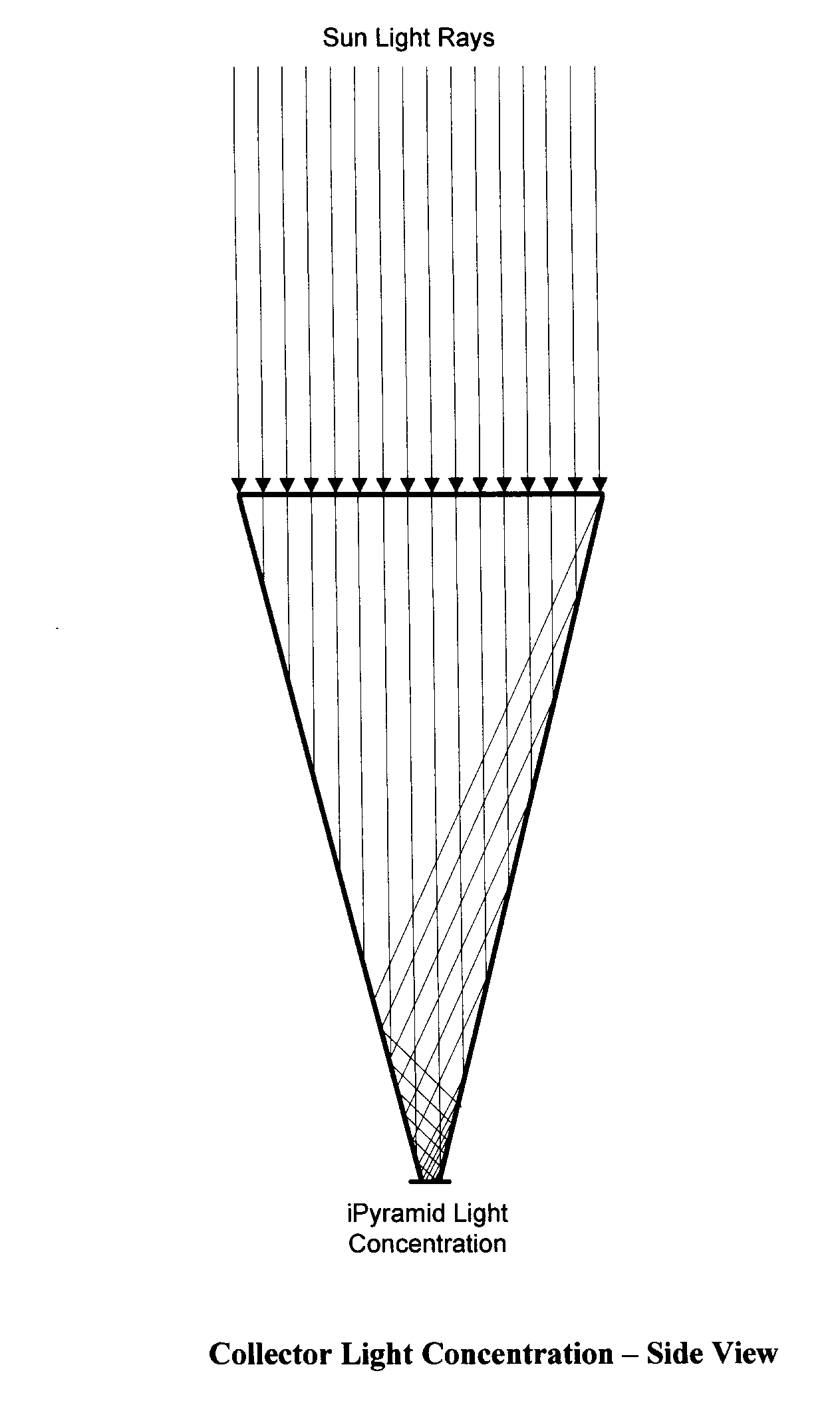
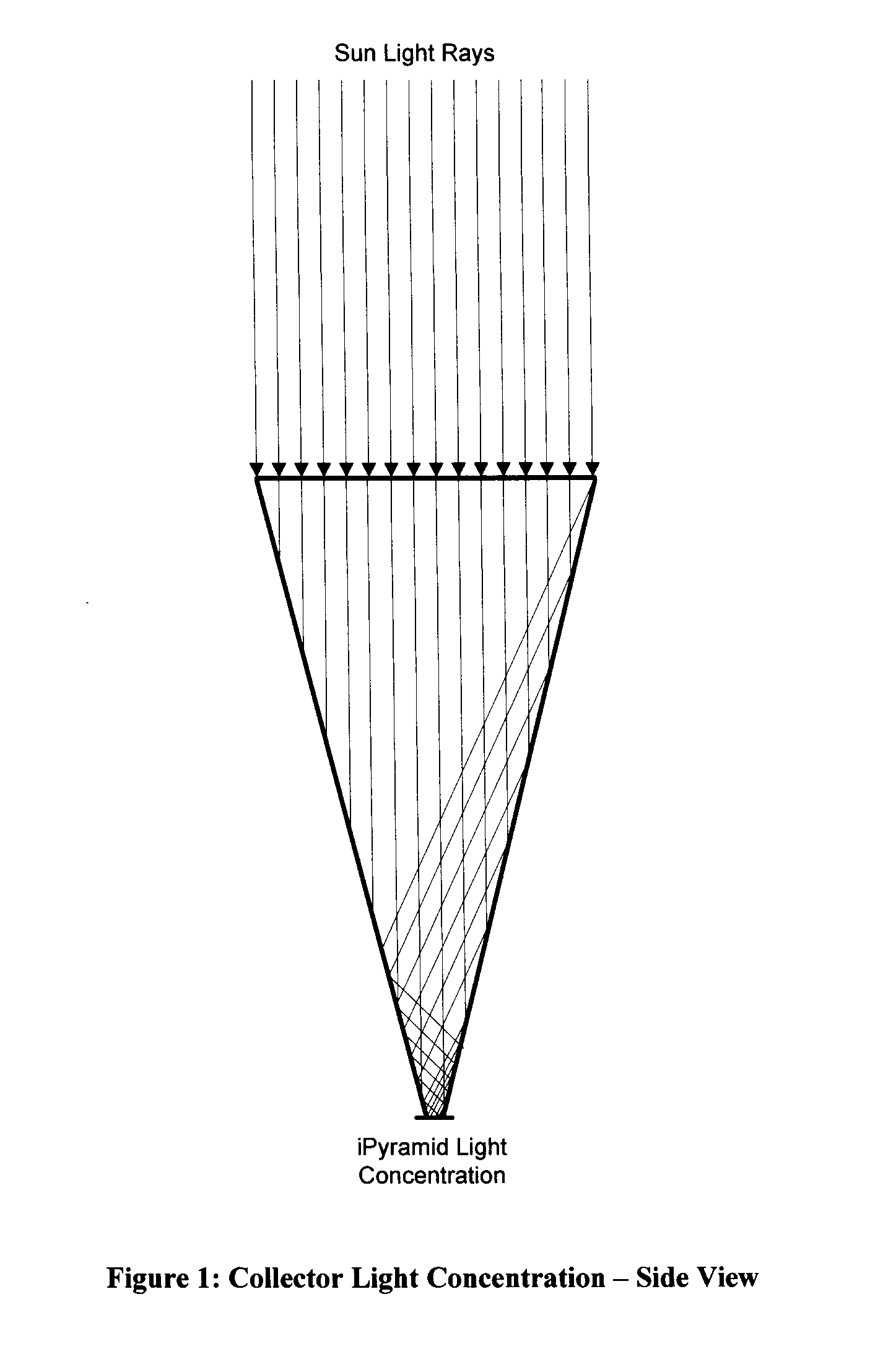
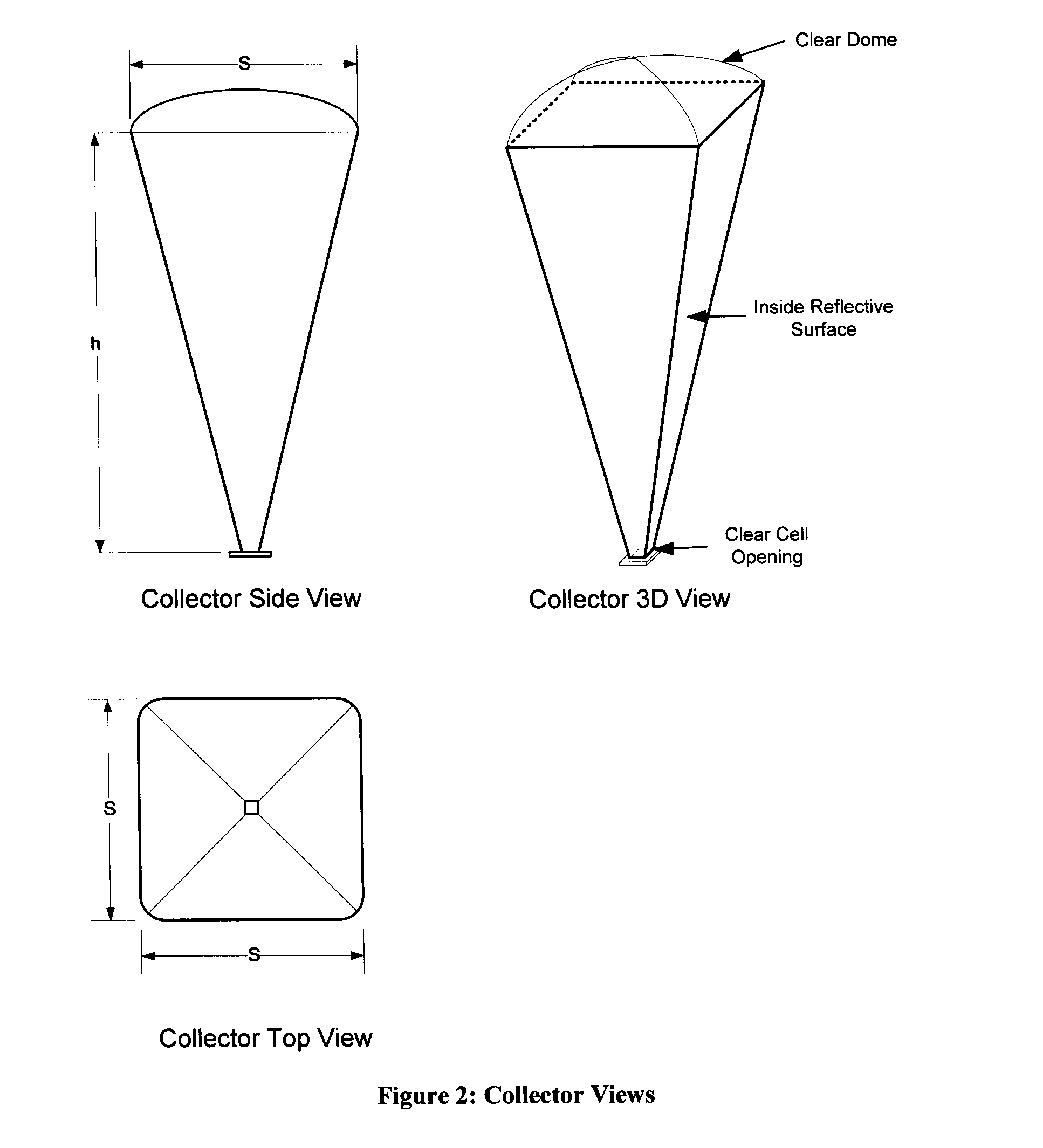
[0116]A solar collector is provided in the form of an inverted symmetrical, truncated, pyramid with a square aperture at its top. A collector gathers the sun's rays and through reflection concentrates them onto a concentrated photovoltaic cell installed at collector's bottom. The inverted pyramid of the collector is truncated by a horizontal plane, at a given height from the apex. For strengthening and preventing a concentration of load at the very bottom, the collector is enclosed into a supporting rigid housing. The housing of the inverted pyramid shape is made of plastic, glass, metal or other sturdy material that provides support to the collector when it tilts and under windy conditions. The height of the housing is sufficient to maintain the collector's shape if the collector is made of a non-rigid material, e.g. balloon or film.

[0117]Collectors are mounted on a rotating pipe and trace out a 180 degree trajectory following the sun, which enters the collectors always under a dir...


PUM


Abstract

There is provided a concentrating solar collector in the shape of an inverted truncated pyramid (collector) with light reflective surfaces on the inside. The collector includes a large top opening which is pointed towards the sun collecting the sun rays. A high-concentration photovoltaic solar cell is placed at the narrow end of the collector. The light is concentrated onto the solar cell, which generates electricity from the concentrated solar light. The collector is made of, but not limited to, an inflatable lightweight reflective film, balloon filled with helium, glass, plastic or metal. The reflective surface inside the collector is obtained using inexpensive mirror coating which is applied to clear glass or plastic. A cooling system is used for keeping the concentrated photovoltaic solar cell at or close to a fixed temperature to maintain the cell at its highest operating efficiency of power generation.

Description

BACKGROUND OF THE INVENTION[0001]The present invention generally relates to concentrated solar systems, concentrating solar light and energy and using a collector in the shape of truncated symmetrical inverted pyramid that concentrates light onto the solar cell positioned at its bottom. The plurality of said collectors is movably mounted on the rotating pipes and arranged into the solar energy generating array. The motion of array components is aimed at effectively capturing the sun's rays and concentrating them onto the solar cells.[0002]Photovoltaic technology is the most promising, alternative energy source, creating electricity with no pollution and no noise. Photovoltaic conversion is useful for several reasons. Conversion from sunlight to electricity is direct, so that bulky mechanical generating systems are unnecessary. The modular structure of the photovoltaic arrays makes them highly scalable, easy to set up and allows adaptation to the site characteristics.[0003]A high-con...

Claims


Application Information

Patent Timeline
IPC IPC(8): H01L31/042F28D15/00H02S40/22F24S23/70H02S20/32H02S40/42
CPCF24J2/10F24J2/16F24J2002/108H01L31/0232H01L31/0547Y02B10/20Y02E10/52H01L31/0543H01L31/024F24S23/70F24S2023/872F24S23/77
Inventor ARAB, RA'EDMASEK, WILLIAM
Owner QUADRA SOLAR CORP
Learn More