Multilayer ceramic electronic component

a technology of electronic components and ceramics, applied in the direction of fixed capacitor details, stacked capacitors, fixed capacitors, etc., can solve the problems of disadvantageous short circuit, cracking to occur in ceramic element assemblies, and short circuit, so as to achieve reliably prevent short circuit in the first effective region, the effect of reliably preventing short circui

Active Publication Date: 2010-09-02
MURATA MFG CO LTD
View PDF14 Cites 24 Cited by
  • Summary
  • Abstract
  • Description
  • Claims
  • Application Information

AI Technical Summary

Benefits of technology

[0029]Accordingly, with the first preferred embodiment, because a crack preferentially occurs from the edge of the second extended section and less frequently occurs from the edge of the first extended section, a short circuit can be reliably prevented in the first effective region.
[0030]With the multilayer ceramic electronic component according to the second preferred embodiment, because the relationships Y1>Y2, X1<Y1<(L−E), and Y2<X2 are satisfied, internal stress resulting from external stress at the second end surface side is greater than that at the first end surface side. Thus, if a crack occurs, it preferentially appears from the edge of the second extended section, not from the edge of the first extended section, so a short-circuit in the first effective region can be reliably prevented.

Problems solved by technology

For a multilayer ceramic electronic component, externally applied stress, such as thermal stress due to a change in external temperature or flexural stress imposed on a mounting board, may cause a crack to occur in a ceramic element assembly.
If the crack runs over the border between internal electrodes coupled to different potentials, a short-circuit may occur.
In that case, a short-circuit disadvantageously occurs.
In that case, a short circuit disadvantageously occurs.

Method used


Image

  • Multilayer ceramic electronic component
  • Multilayer ceramic electronic component
  • Multilayer ceramic electronic component

Examples


Embodiment Construction

[0043]Preferred embodiments of the present invention will be described below with reference to the drawings.

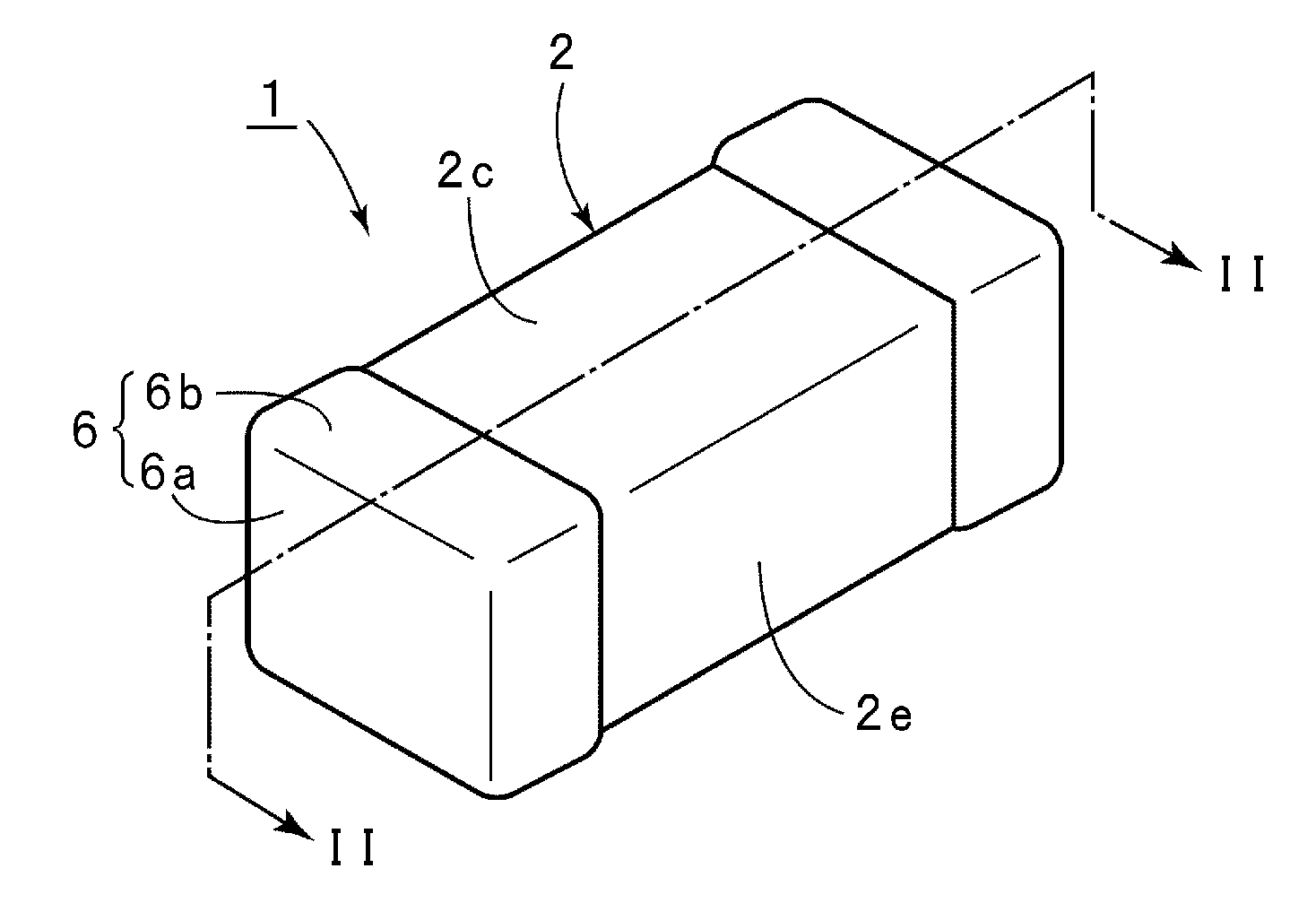
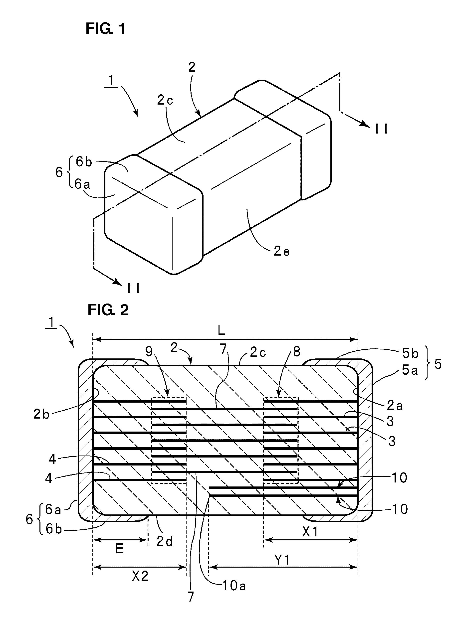
[0044]FIG. 1 is a perspective view that illustrates an external appearance of a multilayer ceramic capacitor as a multilayer ceramic electronic component according to a first preferred embodiment of the present invention. FIG. 2 is a cross-sectional view taken along the line II-II of FIG. 1. A multilayer ceramic capacitor 1 includes a ceramic element assembly 2. The ceramic element assembly 2 is made of a ceramic sinter fired by ceramic integral sintering together with first and second internal electrodes described below.

[0045]The ceramic element assembly 2 preferably has a substantially rectangular parallelepiped shape, for example. The ceramic element assembly 2 has opposed first and second end surfaces 2a and 2b and opposed first and second principal surfaces 2c and 2d. The ceramic element assembly 2 also has a side surface 2e illustrated in FIG. 1 and an opposite side surf...


PUM

PropertyMeasurementUnit
thicknessaaaaaaaaaa
thicknessaaaaaaaaaa
thicknessaaaaaaaaaa

Abstract

A multilayer ceramic capacitor includes first internal electrodes extending to a first end surface of a ceramic element assembly, a plurality of second internal electrodes extending to a second end surface, floating internal electrodes arranged so as to overlap the first and second internal electrodes with ceramic layers disposed therebetween to define first and second effective regions, inner conductors that are elongated from the first end surface beyond a region that overlaps the first effective region in the direction of layering, and a relationship X1<Y1<(L−E) is satisfied where L is the dimension in the longitudinal direction extending from the first end surface to the second end surface, X1 is the longitudinal-direction dimension of each of the first internal electrodes, Y1 is the distance between the first end surface and an end of each of the first internal electrodes, and E is the distance between the second end surface and an end of the second extended section.

Description

BACKGROUND OF THE INVENTION[0001]1. Field of the Invention[0002]The present invention relates to multilayer ceramic electronic components, for example, multilayer ceramic capacitors and multilayer ceramic thermistors, and in particular, to a multilayer ceramic electronic component including a floating internal electrode disposed in a ceramic element assembly and including a plurality of effective regions used to extract capacitance.[0003]2. Description of the Related Art[0004]Automobiles include various incorporated systems, including an engine, an air conditioner, and an air bag system. A plurality of control devices for controlling each of these systems, called electrical control units (ECUs), are incorporated, accordingly. Each ECU has various mounted electronic components. In recent years, with an increase in the number of systems, the number of ECUs incorporated in an automobile has increased. As such, miniaturization of an ECU and an electronic component mounted on the ECU is ...

Claims


Application Information

Patent Timeline
Patent Type & Authority Applications(United States)
IPC IPC(8): H01G4/228H01C7/18
CPCH01G4/012H01G4/30H01G4/12
Inventor SHIMIZU, NAOKI
Owner MURATA MFG CO LTD
Why Eureka
Try Eureka