Remote Control Electric Powered Skateboard

a remote control and electric power technology, applied in the direction of dynamo-electric converter control, motor/generator/converter stopper, instrument, etc., can solve the problems of reducing efficiency and shortening the use life of the battery, affecting the speed of the skateboard, and reducing the efficiency of the battery. , to achieve the effect of slowing down the speed, increasing the speed of the skateboard, and shortening the tim

Inactive Publication Date: 2010-09-02
CHANG WESLEY WENTI
View PDF13 Cites 63 Cited by
  • Summary
  • Abstract
  • Description
  • Claims
  • Application Information

AI Technical Summary

Benefits of technology

[0006]A brushless motor or a brushless hub motor installed on said lower surface of the skateboard connects to a battery device that provides either motor with a driving power therewith through a controller. A driving device is disposed between the brushless motor and at least one of the wheels. The driving device is controlled by a remote control and is able to offer an automatic comparison function: the remote control subjected to electrification allows an automatic generation of an initial code for permitting a receiver in the controller to execute the spontaneous identification and automatically lock the initial code. An automatic decoding is carried on after the remote control is shut off. The receiver receiving control signals emitted from the remote control, the controller thence decodes the signal so as to dispatch distinct commands to the brushless motor, thereby allowing various actions pursuant to the signals emitted from the remote control to be implemented by the skateboard. At least three touch switches disposed on the remote control respectively control an accelerating cruise, a decelerating cruise, and a brake of the brushless motor. Moreover, the brushless motor or the brushless hub motor utilizes an instant obverse-reverse rotation characteristic to trigger the braking motion of the brushless motor or the brushless hub motor. Namely, while a braking signal is emitted from the remote control, the controller would thence emit a counter current to the brushless motor, so that the brushless motor or the brushless hub motor would have a braking function equivalent to a reverse rotation. Alternatively, the remote control adopts a potential sliding stem to emit the control signals to the controller. The potential sliding stem includes a sliding buckle. While the sliding buckle is clutched backward by a finger, an average velocity would be provided. Moreover, the velocity of the skateboard is decided according to a displacement amount of the sliding buckle. When rider feels a specific velocity is suitable, the sliding buckle would not be clutched anymore. While the sliding buckle is moved forward to its original position, a deceleration effect would be achieved; herein, while the sliding buckle is moved frontward to a certain angle, a brake motion would be triggered, and the skateboard would be stopped in a safe short time. If rider desires to back the skateboard, the back switch on the top portion of the remote control should be triggered, and the operating means of the back motion is same as that of the forwarding motion.
[0009]The skateboard adopts the high speed permanent magnet synchronous brushless motor or brushless hub motor, whose highest speed achieves 5100 RPM, as well as the controller. The motor and the controller are fixed under the skateboard. In operation, rider operates the touch buttons on the remote control to dispatch divergent control signals to the controller, so that the brushless motor or the brushless hub motor could execute different working procedure. Herein, at least one rear wheel is connected to a synchronizing wheel on the brushless motor via a synchronizing tape, and at least one rear wheel is directly connected to the brushless hub motor. Finally, various stable actions could be accomplished accordingly. Four touch switches are disposed on the remote control. While the accelerating cruise button is clicked, the skateboard would move with a uniform velocity. The velocity of the skateboard is decided by the clicking times on the button. As a result, while rider feels a certain velocity is suitable, the accelerating cruise button would not be triggered anymore, and then the operation of cruise would start. Herein, the remote control adopts the stepless speed regulation. That is, if rider continuingly presses the accelerating cruise button, the velocity of the skateboard would be steplessly increased until the desired velocity is achieved. The decelerate button has a similar function to that of the accelerate button. The slight difference between abovementioned two buttons is that one is disposed for accelerating and the other is disposed for decelerating. Pressing the reverse button would back the skateboard, and pressing the brake button would stop the skateboard in a short time. The remote control and the controller are able to intercommunicate and control with each other through dual frequencies. At least two brushless motors are disposed in accordance with an active wheel and other passive wheels to collectively form a multi-driving motor system. Moreover, an electrical differential device is disposed in the controller for synchronous rotation of the four wheels.
[0011]The remote handle employs the four touch switches thereon to transmit distinct control signals to the controller. The four touch switches are the accelerating cruise button, the decelerating cruise button, the reverse button, and the brake button. Wherein, the accelerating cruise button is applied to control the acceleration and cruise of the brushless motor or the brushless hub motor, the decelerating cruise button is applied to control the deceleration and cruise of the brushless motor or the brushless hub motor, the reverse button is applied to control the backing motion of the brushless motor or the brushless hub motor, and the brake button is applied to control the braking motion of the brushless motor or the brushless hub motor. Pressing the accelerating cruise button allows the skateboard to be moved with a uniform velocity; the velocity of the skateboard is decided by the clicking times on the button. As a result, while rider feels a certain speed is suitable, the accelerating cruise button would not be triggered anymore, and then the operation of cruise would start. Herein, the remote control adopts the stepless speed regulation. That is, if rider continuingly presses the accelerating cruise button, the velocity of the skateboard would be steplessly increased until the desired velocity is achieved. Pressing the decelerate button would slow down the velocity, pressing the reverse button would back the skateboard, and pressing the brake button would stop the skateboard in a short time. The remote control adopts a potential sliding stem to emit the control signals to the controller; the potential sliding stem includes a sliding buckle whose displacement amount decides a self-velocity of the skateboard. Rider's finger triggering the buckle inwardly allows the skateboard to be moved with a uniform velocity. If a desired speed of the skateboard is reached, rider would not clutch the buckle anymore for reducing the speed thereof. Moreover, a backing motion of the skateboard could be accomplished by a reverse clutching from the rider. Thus, when the sliding buckle is moved outward to a certain angle, a brake motion of the skateboard would be triggered and the skateboard would be stopped in a short time.

Problems solved by technology

Herein, the moveable trigger on the remote control has a shorter movable distance, so such operation means is difficult for beginners to use.
Further, the motors contained in such electric powered skateboard adopt common brush motors which possess the characteristics of the lower efficiency and shorter using life.
Especially, suchlike battery is unable to sustain the large current applied in the controller of the brushless motor.
As a result, the battery would adversely have a shorter using life.

Method used


Image

  • Remote Control Electric Powered Skateboard
  • Remote Control Electric Powered Skateboard
  • Remote Control Electric Powered Skateboard

Examples


Embodiment Construction

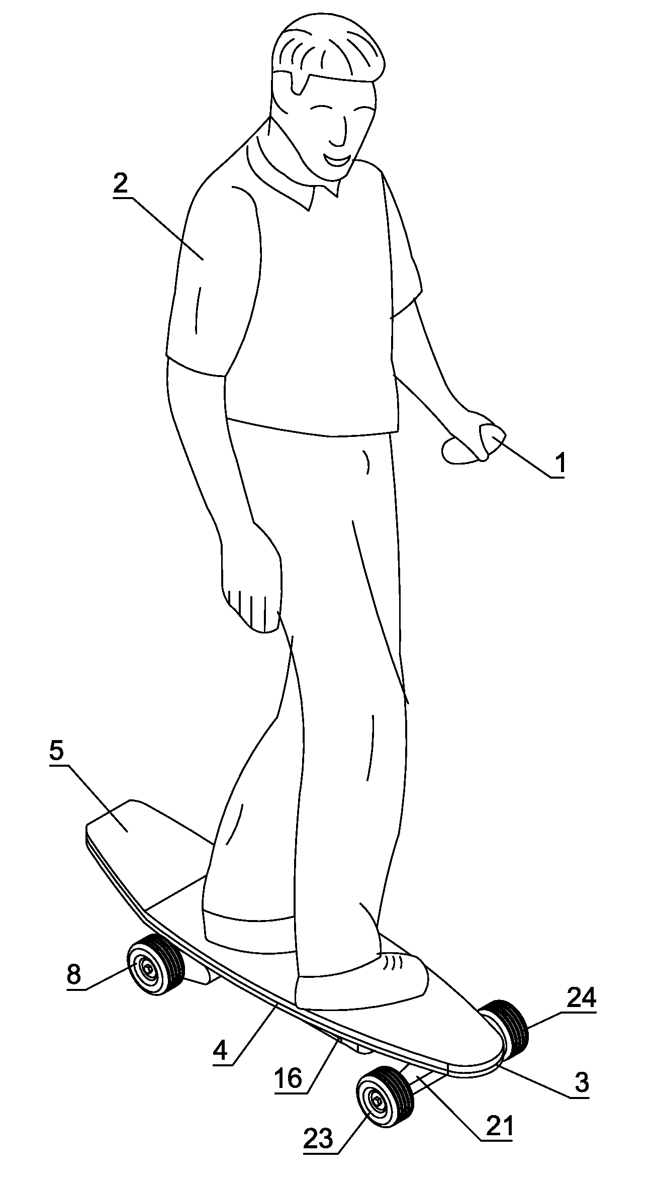
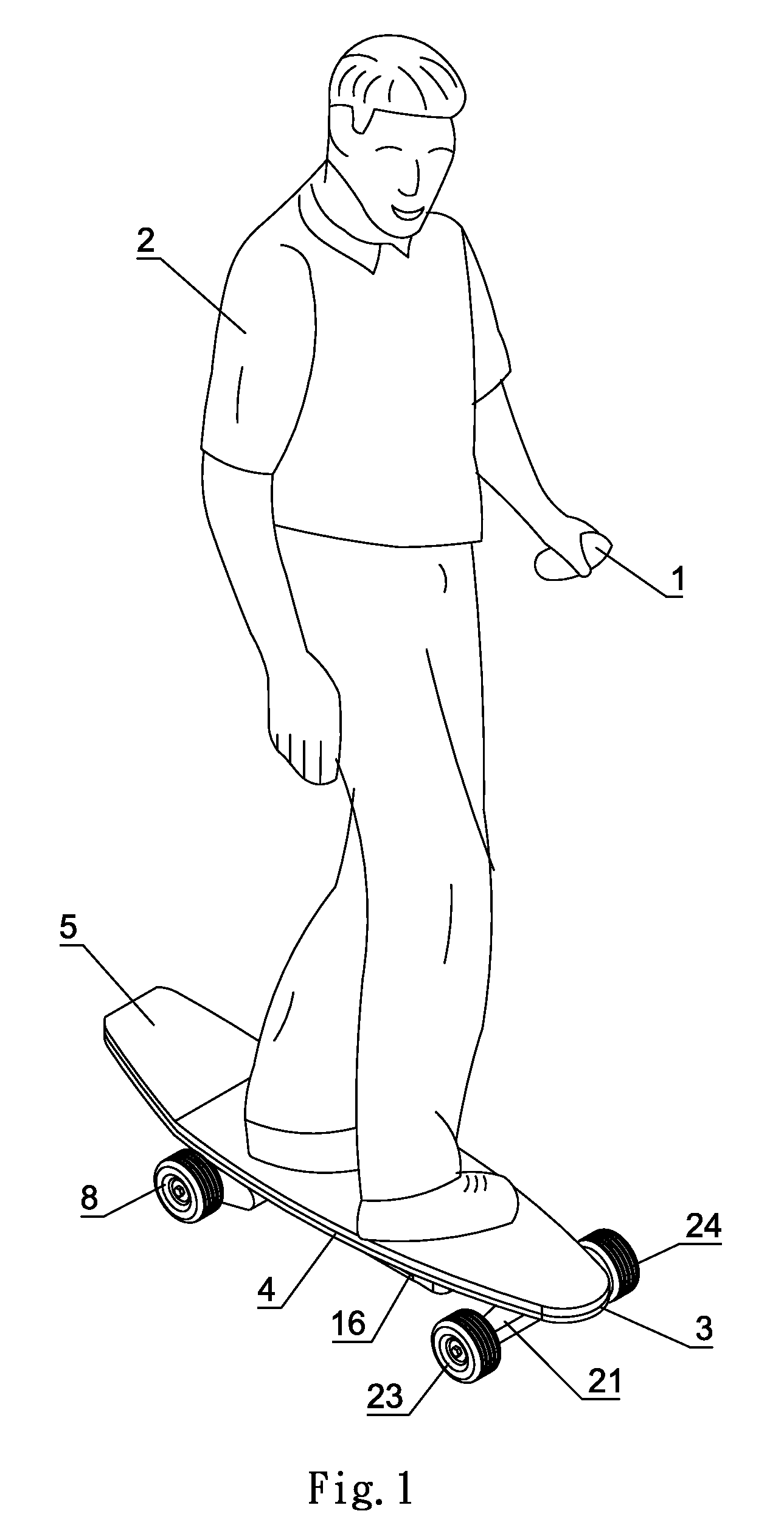
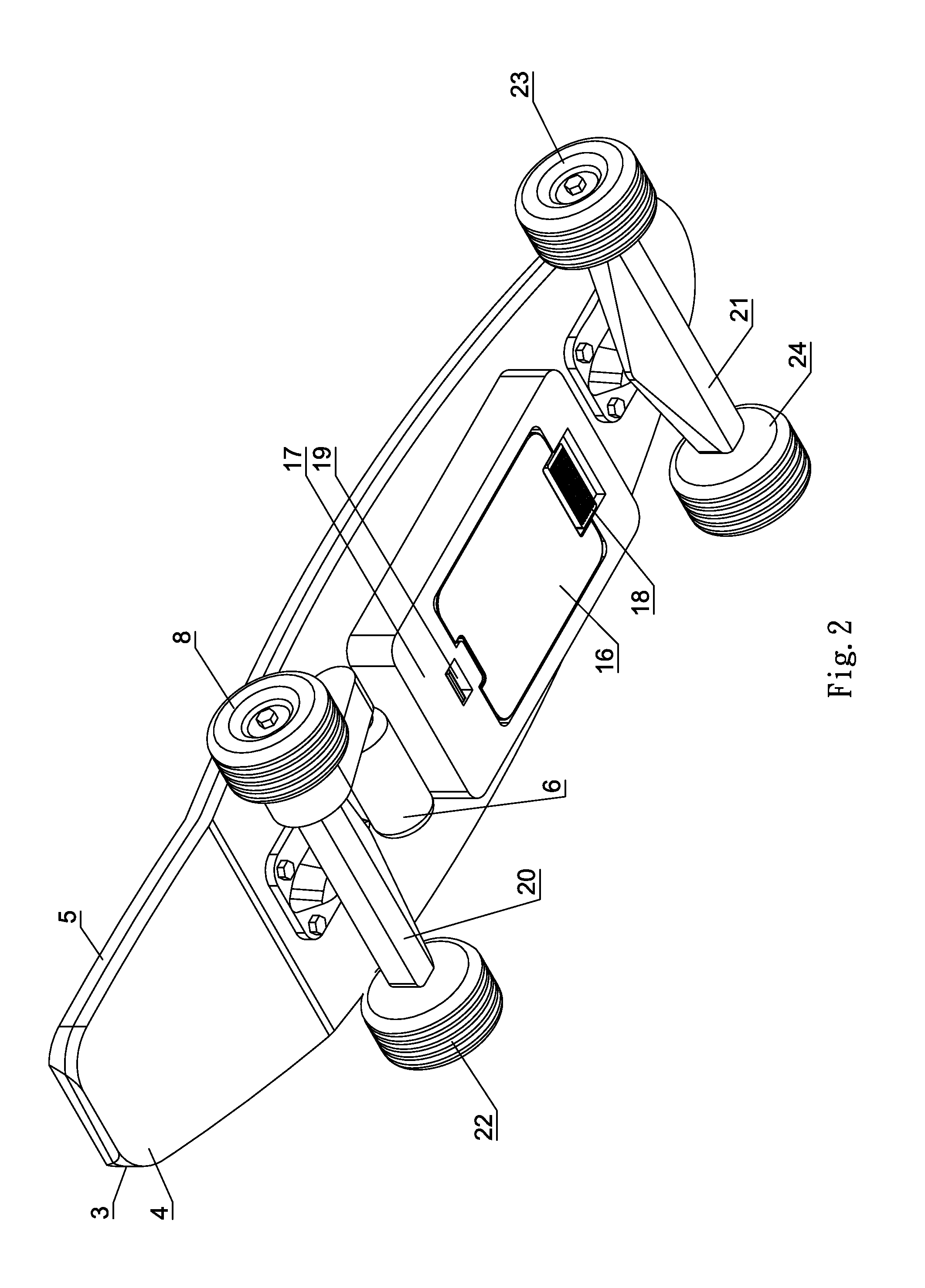
[0028]FIG. 1 shows a first preferred embodiment of the present invention. A rider 2 with a remote control 1 stands on a skateboard (as shown in FIG. 2). More detailed structures could be illustrated in FIGS. 2 to 4. The skateboard comprises a regular plywood 3 disposed at an upper portion thereof. As it should be, the plywood 3 could be made of other materials, like a polymer filled with glass. Herein, the plywood 3 has an upper rider-support surface 5 and a lower surface 4 supporting a front support 21, a plurality of passive wheels 23, 24, a rear support 20, a active wheel 8, and a passive wheel 22. Also, a transmitting apparatus, namely, a brushless motor 6, a controller 17, and a battery box 16 with Li-ion battery are all included in the present invention.

[0029]Referring to FIGS. 2 and 7, the electric powered skateboard has a synchronizing wheel 61 installed on a rotor of the brushless motor 6. Herein, by means of a synchronizing tape 10, the active wheel 8 could be directly rot...


PUM


Abstract

A remote control electric powered skateboard has a brushless motor or a brushless hub motor installed on the lower surface of the skateboard for connecting to a battery device through a controller, so that the motors could be electrified. A driving device disposed between either afore motors and at least one wheel is controlled by the remote control, thereby permitting an automatic comparison. When the electrification of the remote control executes, the remote control spontaneously generates an initial code for a receiver in the controller to robotically distinguish and lock the code. Turning off the remote control provides an automatic decoding. A receiver receives control signals from the remote control for the controller to interpret, and accordingly the controller generates and sends distinct commands to either motor, which allows the skateboard to implement various actions correspondingly. An auxiliary remote device disposed on the joint between a front support and a plywood is foldable or could stand on the skateboard; the height of the auxiliary remote device is adjustable for meeting divergent demands from dissimilar riders. A remote handle further provides the same operating means as that of the remote control for offering a supplementary supporting function.

Description

BACKGROUND OF THE INVENTION[0001]1. Field of the Invention[0002]The present invention relates to a remote control electric powered skateboard, in particular to a power-driven skateboard.[0003]2. Description of the Related Art[0004]Skateboards are a popular way for young persons to travel. Even though electric powered skateboards could be widely seen in the market, certain deficiencies are admitted in the conventional electric powered skateboards. Such remote control electric powered skateboard issued by a U.S. Pat. No. 5,893,425 includes a remote control having a movable trigger. Wherein, the movable trigger is able to emit a variable controlled acceleration signal and a variable controlled deceleration signal according to the displacement amount of the trigger. Moreover, a motor includes a motor control and a receiving device that receives the variable controlled acceleration signal and the variable controlled braking signal, so that the motor could be adjustably accelerated and br...

Claims


Application Information

Patent Timeline
Patent Type & Authority Applications(United States)
IPC IPC(8): A63C17/12H02P1/18
CPCA63C17/015A63C17/12Y02T10/648B60L15/42A63C2203/22Y02T10/64
Inventor CHANG, WESLEY WENTI
Owner CHANG WESLEY WENTI
Why Eureka
Try Eureka