Solar cell device structure

Inactive Publication Date: 2010-09-09
INST NUCLEAR ENERGY RES ROCAEC
View PDF2 Cites 11 Cited by
  • Summary
  • Abstract
  • Description
  • Claims
  • Application Information

AI Technical Summary

Benefits of technology

[0009]A major objective of the present invention is to provide a solar cell device structure, wherein, silicon substrate is utilized as a carrier substrate for a solar cell, and it is also utilized as a heat dissipation substrate for dissipating the heat of high temperature generated during operation by making use of merits and advantages of silicon substrate: superior heat conduction capability, low production cost, and maturity of semiconductor manufacturing technology for silicon, thus raising its heat dissipation capability and efficiency.
[0010]Another objective of the present invention is to provide a silicon substrate of heat conductivity of 124 W / m·K utilized in producing concentrator solar cell device structure, that is a considerable improvement over the ceramic substrate of heat conductivity of 30 W / m·K of the prior art having the shortcomings that, heat is liable to accumulate in the substrate, thus reducing the photo-to-electrical-energy conversion efficiency of the solar cell thus produced.
[0011]A yet another objective of the present invention is to provide a silicon substrate used for manufacturing solar cell device structure, and that is used to replace the ceramic substrate of the prior art, so as to solve the shortcomings of inferior heat dissipation efficiency of ceramic substrate, since that could incur the problems of having to install additional heat dissipating plates, hence increasing the complexity of manufacturing processes and raising the production cost.

Problems solved by technology

However, in proceeding with photo-to-electrical-energy conversion utilizing a concentrator solar cell, due to the restrictions of light absorption capability of the material utilized to a certain section of spectrum, thus the input optical energy can not be converted to output electrical energy in its entirety.
Though temperature increase will cause an increase of possibility of carrier generation; yet, in contrast, the increase of temperature will cause a significant increase of dark current inside a solar cell, and that would in turn reduce the efficiency of conversion from solar energy to electrical energy.
Since significant heat of high temperature will be generated while solar cell 13 and circuit layout layer 12 are in operation, yet, the inferior heat conduction capacity of a ceramic substrate 11 is not sufficient to transfer the heat thus generated properly into the outside air, hereby resulting in inferior photo-to-electrical-energy conversion efficiency.
However, by doing so, not only the complexity of manufacturing processes is increased, but the production cost is also raised.
For the reasons mentioned above, it is evident that the functions and performances of solar cell of the prior art are not quite satisfactory, thus it has much room for improvements.

Method used


Image

  • Solar cell device structure
  • Solar cell device structure
  • Solar cell device structure

Examples


Embodiment Construction

[0018]The purpose, construction, features, functions, and advantages of the present invention can be appreciated and understood more thoroughly through the following detailed description with reference to the attached drawings.

[0019]In the following, please refer to the related drawings together with detailed descriptions in describing a solar cell device structure according to an embodiment of the present invention. For easy reference and understanding, similar reference numerals are utilized to refer to similar elements.

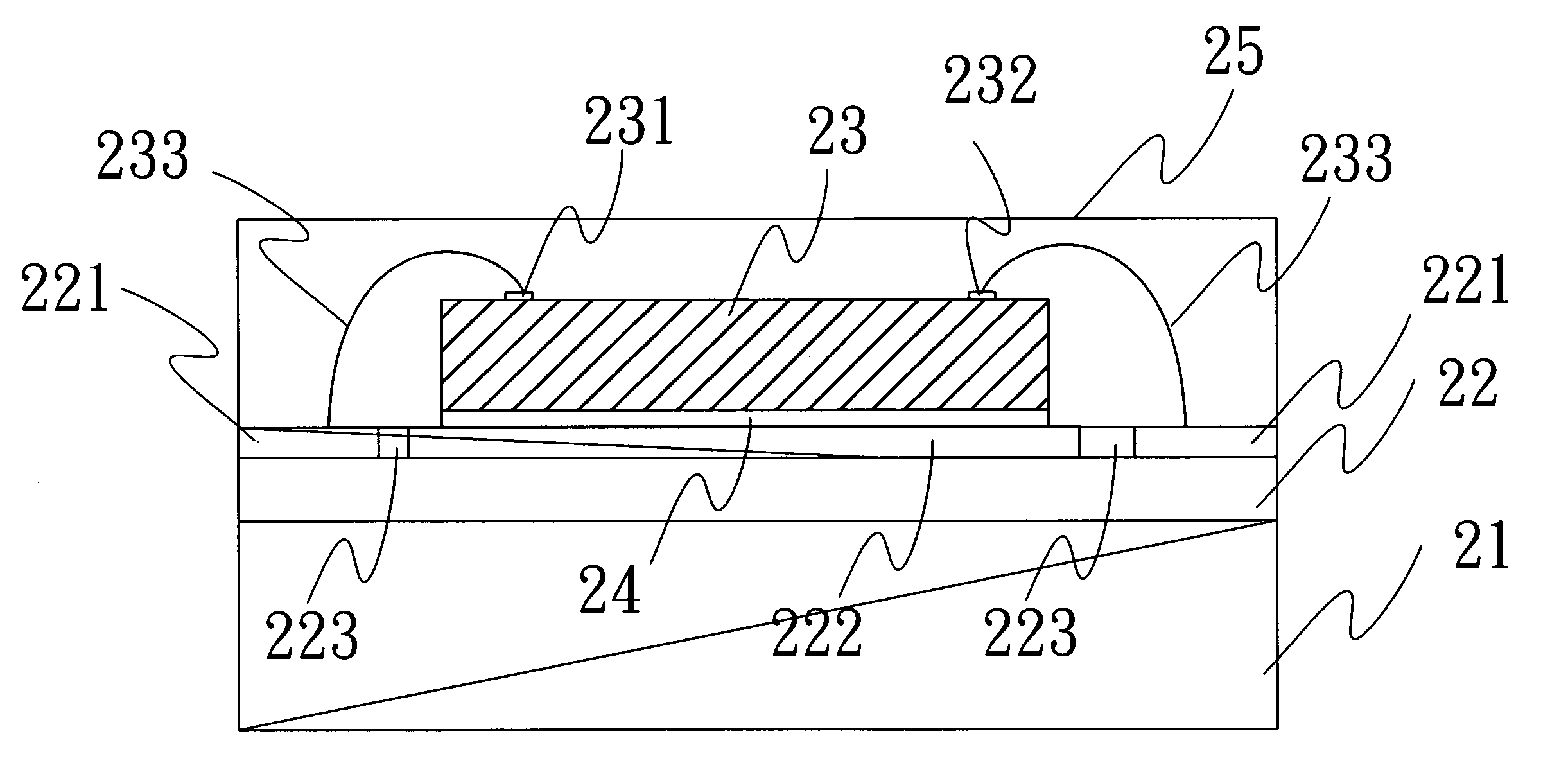
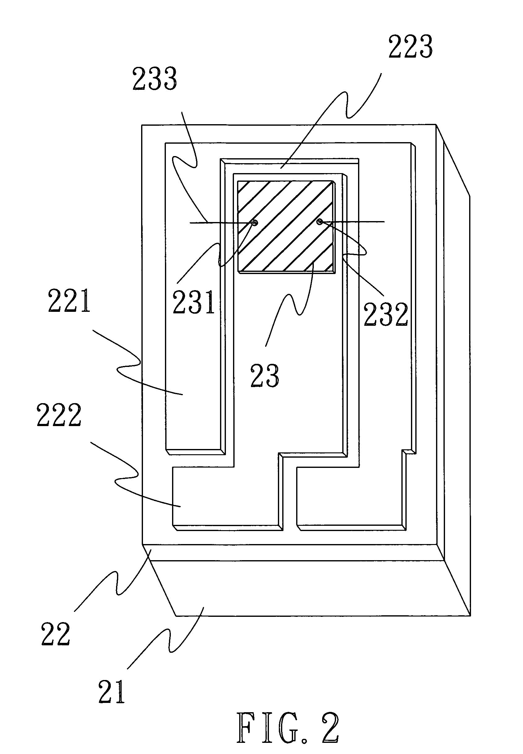
[0020]In the following descriptions, please refer to FIGS. 2 & 3 simultaneously. Wherein, FIG. 2 is a perspective view of solar cell device structure according to an embodiment of the present invention; and FIG. 3 is a cross section view of a solar cell device structure according to an embodiment of the present invention. As shown in FIGS. 2 & 3, the solar cell device structure of the present invention is applicable to a concentrator solar cell device structure. Wh...


PUM


Abstract

A solar cell device structure, that is applicable in a concentrator solar cell device structure, comprising a silicon substrate, an insulation layer, and a solar chip. Wherein, the insulation layer is provided on the silicon substrate, a pattern region is provided on the insulation layer, and the solar chip is disposed in the pattern region. Due to the various advantages of superior heat conduction, low cost, and maturity of silicon semiconductor manufacturing technology of a silicon substrate, it is utilized to replace the ceramic substrate of the prior art, hereby raising the heat dissipation efficiency and reducing the production cost.

Description

BACKGROUND OF THE INVENTION[0001]1. Field of the Invention[0002]The present invention relates to a solar cell device structure, and in particular to a solar cell (photovoltaic cell) device structure capable of raising its heat dissipation efficiency by making use of a silicon substrate.[0003]2. The Prior Arts[0004]In recent years, along with the rapid progress and improvements of living standard, the demand of energy consumption has been increasing rapidly. However, since the traditional energy resources on earth are drained nearly to their depletion, so that in this situation, various re-generable energy resources are developed to meet the energy requirements. Among them, solar energy is most prominent and important one, and is getting most of the attention. In general, solar-energy-electricity-generation is realized through a kind of solar cell made of semiconductor materials, thus converting solar energy into electrical energy.[0005]For a more advanced model solar cell, a concent...

Claims


Application Information

Patent Timeline
IPC IPC(8): H01L31/00
CPCH01L31/02008Y02E10/50H01L31/052H01L31/048
Inventor HONG, HWEN-FENLEE, YUEH-MUTSAI, SHANG-YUKUO, CHERNG-TSONG
Owner INST NUCLEAR ENERGY RES ROCAEC
Why Eureka
Try Eureka