Apparatus and process for integrated gas blending

Inactive Publication Date: 2010-09-09
ENTEGRIS INC
View PDF54 Cites 63 Cited by
  • Summary
  • Abstract
  • Description
  • Claims
  • Application Information

AI Technical Summary

Benefits of technology

[0056]a pressure controller arranged to control flow of the other of the active and diluent fluids so

Problems solved by technology

This gas supply approach has the following deficiencies:(1) the gas supply vessels are exhausted at a high rate, requiring numerous change-outs of the gas supply vessels during the operation of the active gas-consuming process;(2) when gas supply vessels are changed out as they are exhausted, the active gas-consuming process may need to be re-qualified, since the concentration of active gas supplied from a freshly installed gas supply vessel may be different from the concentration dispensed from a previously installed gas supply vessel;(3) in addition to deficiency (2), the gas concentration of the active gas dispensed from any given gas supply vessel is fixed by the gas supply vessel manufacturer, and there is no capability of delivering varying concentrations depending on time-varying conditions in the downstream active gas-consuming process;(4) the concentration of the active gas in the gas mixture stored in the gas supply vessel can change with time due to decomposition of the active gas component, or the concentration of the active gas can vary with successive change-outs of gas supply vessels, in an unknown and unexpected manner, and(5) the gas supply vessel typically is at high atmospheric pressure to maximize inventory of the active gas in the vessel, entailing a potentially unsafe situation if the gas supply vessel ruptures or leakage from the associated head assembly, valves, etc. of the vessel occurs.
In-situ gas generation has the following associated deficiencies:(1) the time required to initiate gas generation and achieve steady-state gas production is generally substantial and does not permit a quick-response turn-on of gas dispensing to be achieved;(2) the raw materials used as reactants for in-situ gas generation are frequently highly toxic in character, thereby raising safety and operational issues;(3) in-situ gas generators are typically relatively complex systems, including for ex

Method used


Image

  • Apparatus and process for integrated gas blending
  • Apparatus and process for integrated gas blending

Examples


Embodiment Construction

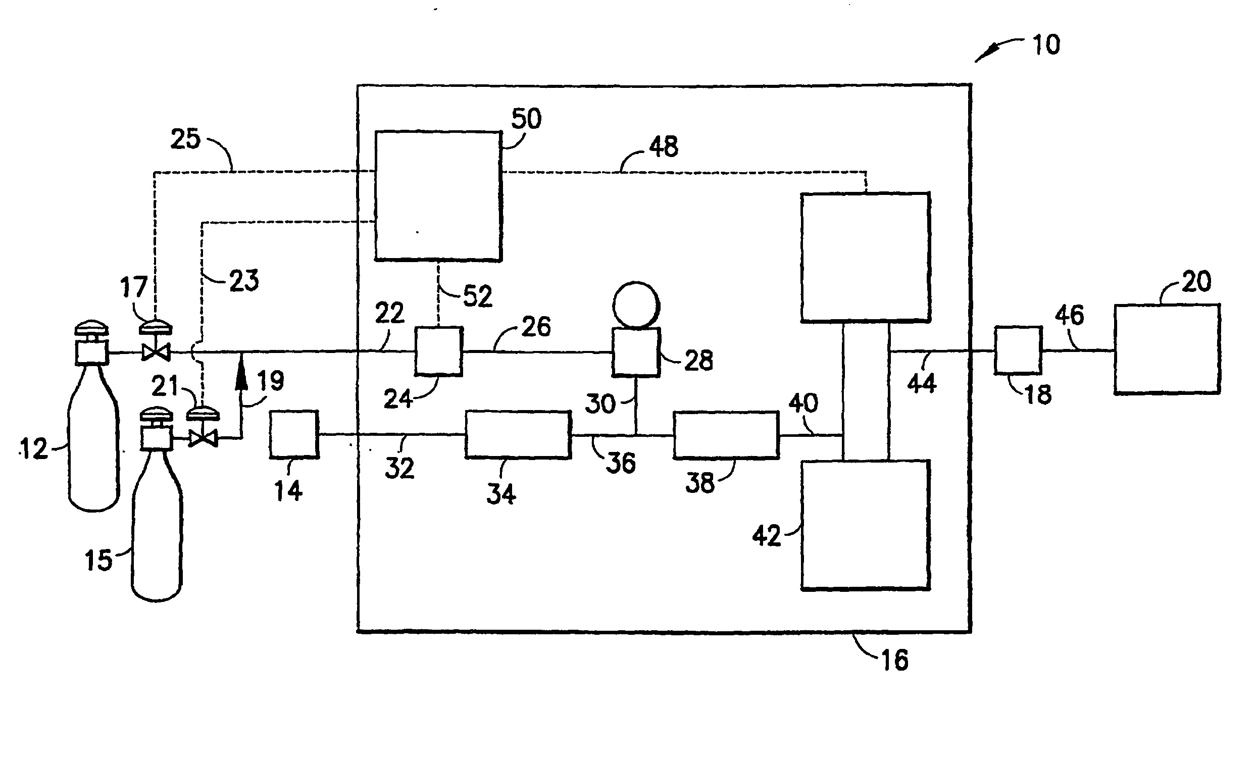
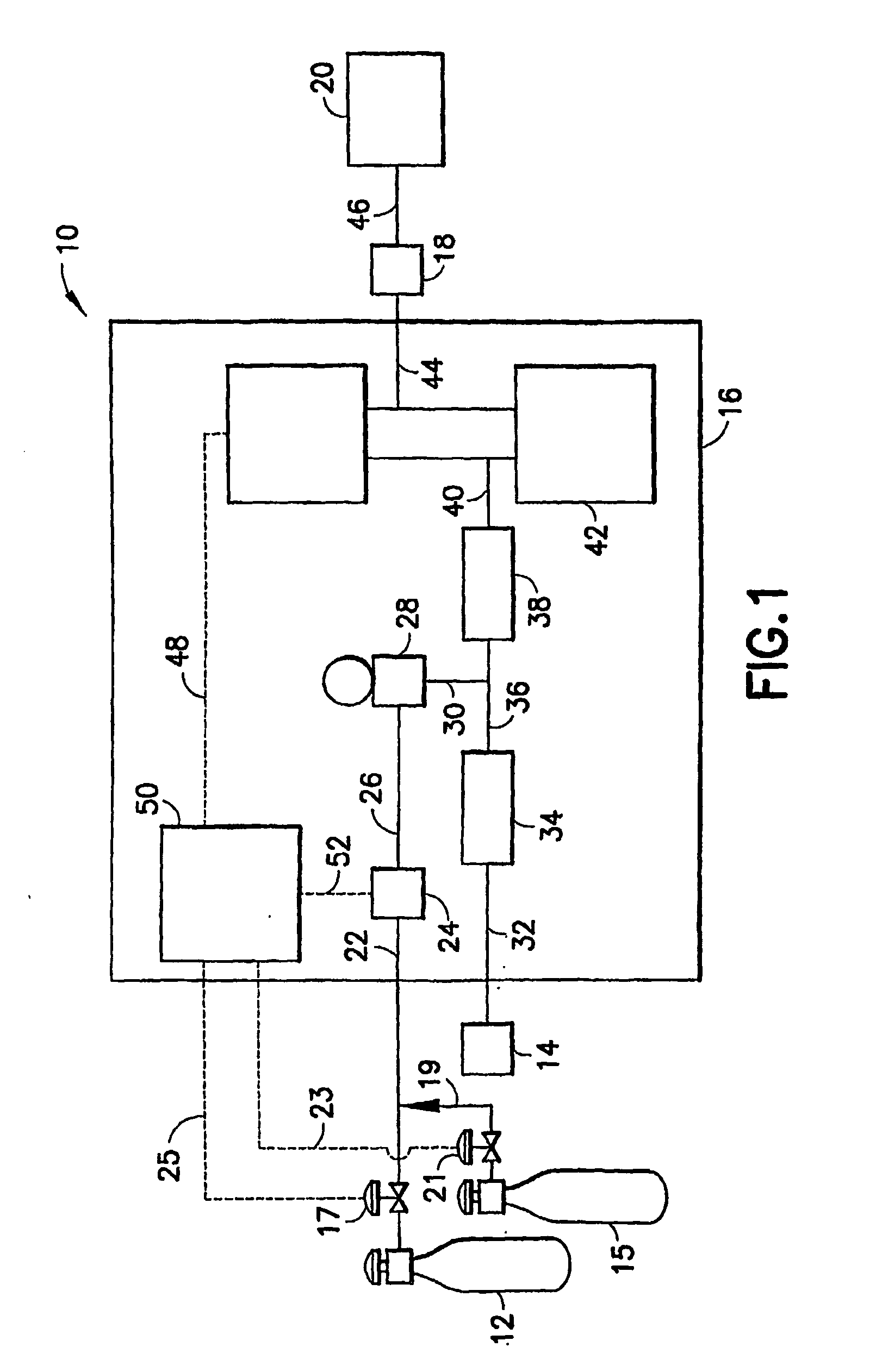
[0059]The disclosures of U.S. Pat. No. 6,909,973 issued Jun. 20, 2005 in the name of Jose I. Arno for “Photometrically Modulated Delivery of Reagents,” and U.S. Pat. No. 7,063,097 issued Jun. 20, 2006 in the names of Jose I. Arno, et al. for “In-Situ Gas Blending and Dilution System for Delivery of Dilute Gas at a Predetermined Concentration” are hereby incorporated herein by reference in their entireties, for all purposes.

[0060]The present invention provides a system for delivery of dilute fluid, utilizing an active fluid source, a diluent fluid source, a fluid flow metering device for dispensing of one of the active and diluent fluids, a mixer arranged to mix the active and diluent fluids to form a diluted active fluid mixture, and a monitor arranged to sense concentration of active fluid and / or diluent fluid in the diluted active fluid mixture, and responsively adjust the fluid flow metering device to achieve a predetermined concentration of active fluid in the diluted active flu...


PUM

PropertyMeasurementUnit
Pressureaaaaaaaaaa
Flow rateaaaaaaaaaa
Concentrationaaaaaaaaaa

Abstract

A system (10) for delivery of dilute fluid, utilizing an active fluid source (12), a diluent fluid source (14), a fluid flow metering device (24) for dispensing of one of the active and diluent fluids, a mixer (28) arranged to mix the active and diluent fluids to form a diluted active fluid mixture, and a monitor (42) arranged to sense concentration of active fluid and/or diluent fluid in the diluted active fluid mixture, and responsively adjust the fluid flow metering device (24) to achieve a predetermined concentration of active fluid in the diluted active fluid mixture. A pressure controller (38) is arranged to control flow of the other of the active and diluent fluids so as to maintain a predetermined pressure of the diluted active fluid mixture dispensed from the system. The fluid dispensed from the system then can be adjustably controlled by a flow rate controller, e.g., a mass flow controller, to provide a desired flow to a fluid-utilizing unit, such as a semiconductor process tool. An end point monitoring assembly is also described, for switching fluid sources (12, 15) to maintain continuity of delivery of the diluted active fluid mixture.

Description

BACKGROUND OF THE INVENTION[0001]1. Field of the Invention[0002]The present invention relates to apparatus and method for supplying dilute gases at predetermined concentrations, e.g., as source gas for ion implantation doping of semiconductor or other microelectronic device materials.[0003]2. Description of the Related Art[0004]The semiconductor industry uses a wide variety of dilute gases in applications where the source material is highly toxic or hazardous and the dosage of active gas species is small.[0005]For instance, ion implantation doping of epitaxial films by requires source gases such as arsine, phosphine, and germane in highly dilute states. As an example, arsenic may be implanted in a semiconductor film for doping thereof, from a dilute arsine / hydrogen gas mixture. In such arsenic doping application, a source gas of low arsine content e.g., 50 parts per million (ppm) may be further diluted with hydrogen to achieve a desired hydrogen / arsine gas mixture. The flows of the ...

Claims


Application Information

Patent Timeline
IPC IPC(8): G05D11/00A23G9/28B01F23/10B67D99/00
CPCB01F3/028H01L21/2225B01F15/0022B01F15/00285B01F15/0429F17C5/06F17C7/02F17C13/02F17C13/025F17C2221/01F17C2221/03F17C2223/0123F17C2223/035F17C2225/0123F17C2225/035F17C2227/0157F17C2250/032F17C2250/043F17C2250/0443F17C2250/0447F17C2250/0452F17C2250/0626F17C2265/025F17C2270/0518G05D11/132B01F15/00207Y10T137/87571Y10T137/2509B01F23/191B01F35/213B01F35/2202B01F35/2132B01F35/833H01L21/02H01L21/22
Inventor HOMAN, JEFFREY J.ARNO, JOSE I.SWEENEY, JOSEPH D.
Owner ENTEGRIS INC
Why Eureka
Try Eureka