Process and apparatus for feeding cementitious slurry for fiber-reinforced structural cement panels

Active Publication Date: 2010-09-09
UNITED STATES GYPSUM CO
View PDF53 Cites 20 Cited by
  • Summary
  • Abstract
  • Description
  • Claims
  • Application Information

AI Technical Summary

Benefits of technology

[0018]The present invention fulfills the same objective as the old slurry headbox, namely providing a robust slurry curtain across the width of the product being formed The invention at hand accomplishes this with no motors or limit switches, a foot print of about 1.5 linear feet,

Problems solved by technology

However, a drawback of such conventional panels is that they do not have sufficient structural strength to the extent that such panels may be comparable to, if not stronger than, structural plywood or oriented strand board (OSB).
The arrangement would not be operable with a cement slurry which contains lumps and chips and which is fast setting.
This arrangement would cause plugging of the area between the curtains, resulting in a broken curtain of slurry deposited on the web.
However, certain problems and deficiencies associated with this technology include numerous electrical contr

Method used


Image

  • Process and apparatus for feeding cementitious slurry for fiber-reinforced structural cement panels
  • Process and apparatus for feeding cementitious slurry for fiber-reinforced structural cement panels
  • Process and apparatus for feeding cementitious slurry for fiber-reinforced structural cement panels

Examples


second embodiment

of a Production Line

[0110]The incorporation of a volume fraction of loose fibers distributed throughout the slurry 46 is an important factor in obtaining desired panel strength. Thus, improved efficiency in incorporating such fibers is desirable. It is believed the system depicted in FIG. 1 in some cases requires excessive numbers of slurry layers to obtain an SCP panel having sufficient fiber volume fraction.

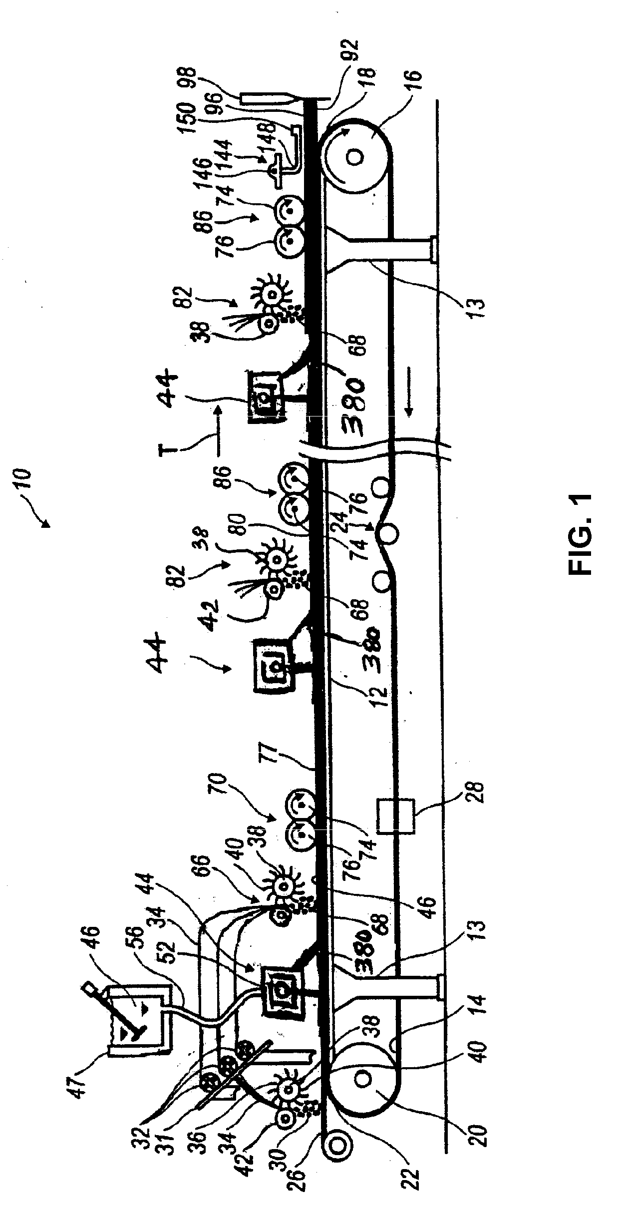
[0111]Accordingly, an alternate SCP panel production line or system is illustrated in FIG. 8 and is generally designated 130 for producing high-performance, fiber reinforced SCP panels incorporating a relatively high volume of fibers per slurry layer. In many cases, increased levels of fibers per panel are obtained using this system. While the system of FIG. 1 discloses depositing a single discrete layer of fibers into each subsequent discrete layer of slurry deposited after the initial layer, the production line 130 includes a process of building up multiple discrete reinforci...

example 1

[0175]The process of co-pending U.S. patent application Ser. No. 11 / 655,647 was run using the basic production line 130 shown in FIG. 8 with the only modification from the process in the co-pending application being the use of the headbox 44 of the present invention in place of the slurry feeds system described in the co-pending application. The cements portion of the slurry comprises 65 wt. % Calcium sulfate alpha hemihydrate, 22 wt. % Type III Portland cement, 12 wt. % Silica Fume, and 1 wt. % hydrated lime. The liquid portion of the slurry comprises 99.19 wt. % water and 0.81 wt. % ADVACAST superplasticizer by W.R. Grace and Co. The liquid:cement weight ratio was 0.55 and the Aggregate (EXTENDOSPHERES SG microspheres):Cement weight ratio was 0.445.

[0176]The slurry was produced according to the present process, using the present system, and is shown to have four slurry layers, 77, 80, 88 and 90, as shown in FIG. 2. This panel should be considered exemplary only in that a panel 92 ...


PUM

PropertyMeasurementUnit
Angleaaaaaaaaaa
Depthaaaaaaaaaa
Distanceaaaaaaaaaa

Abstract

An apparatus and process for depositing slurry upon a moving forming web. The apparatus includes a pivotally mounted headbox for depositing slurry from the inner bottom surface of the headbox down an inclined spillway as a continuous curtain onto a moving web. The headbox is mounted transverse to the direction of travel of the moving web. The headbox also has vertical edge boards, including a headbox back edge board and two opposed headbox side edgeboards, on three respective sides of the headbox to prevent slurry from spilling over the sides and back of the headbox. The headbox is supplied with slurry from a slurry mixer by a feed line mounted on a reciprocating trolley which moves, transverse to the direction of travel of the moving web, back and forth along the length of the headbox.

Description

FIELD OF THE INVENTION[0001]This invention relates to a continuous process and related apparatus for producing structural panels using settable slurry, and more specifically, to an improved slurry feeder headbox apparatus used in the manufacture of reinforced cementitious panels, referred to herein as structural cement panels (SCP), in which fibers are combined with quick-setting slurry for providing flexural strength.BACKGROUND OF THE INVENTION[0002]Cementitious panels have been used in the construction industry to form the interior and exterior walls of residential and / or commercial structures. The advantages of such panels include resistance to moisture compared to standard gypsum-based wallboard. However, a drawback of such conventional panels is that they do not have sufficient structural strength to the extent that such panels may be comparable to, if not stronger than, structural plywood or oriented strand board (OSB).[0003]Typically, the cementitious panel includes at least ...

Claims


Application Information

Patent Timeline
IPC IPC(8): B05D1/30B05C5/00
CPCB28B1/526B28B5/027B28B13/02B28B19/0092Y10S118/04B05C5/0245B28B2013/024B28B2013/0265B05C5/005Y02W30/91
Inventor FRANK, WILLIAM A.BLYSKIS, ALFREDAS
Owner UNITED STATES GYPSUM CO
Why Eureka
Try Eureka