Apparatus for cooling an exerciser for use with an exercise machine

a technology for exercising equipment and exercise machines, applied in gymnastic exercise, ventilation systems, heating types, etc., can solve the problems of reducing the amount of exercise undertaken by many individuals, reducing the health benefits of exercise, and being too cold for individuals just beginning exercis

Inactive Publication Date: 2010-09-09
GOLDMANN RICHARD DR
View PDF61 Cites 25 Cited by
  • Summary
  • Abstract
  • Description
  • Claims
  • Application Information

AI Technical Summary

Benefits of technology

[0009]Various embodiments include a plurality of independent airflow directors that enable chilled air to be directed onto the exerciser from multiple directions, thereby improving the efficiency and uniformity of cooling of the exerciser while improving the localization of the cooling to the immediate region of the exercise machine. In some embodiments, a partial wall or other structure is included that tends to confine the chilled air to a region immediately surrounding the exerciser. Other embodiments include an air return vent that removes and recirculates chilled air from the region surrounding the exerciser, thereby limiting the impact of the chilled air on other, nearby exercisers and on the surrounding environment. And some embodiments include multiple, independent airflow directors are connected to a common source of chilled air and provide cooling to a plurality of exercise machines.

Problems solved by technology

However, exercise is generally accompanied by a certain degree of discomfort, including overheating, sweating, fatigue, etc, and this leads to a significant reduction in the amount of exercise undertaken by many individuals, thereby reducing the health benefits derived from exercise.
Attempts are sometimes made to increase the comfort of exercising individuals in these environments by optimizing the surrounding temperature, but this can be largely unsatisfactory because exercisers generally require different degrees of cooling depending on individual physiology and on how long and how vigorously they have been exercising.
And if the surrounding air is cool enough to be comfortable for an individual who has been exercising vigorously for a significant amount of time, it will be too cold for individuals just beginning to exercise.
However, such fans can provide only a small amount of cooling, and they are typically limited to cooling only the face of the exerciser, and / or some other fixed, limited region of the exerciser's body.
Also, many exercise machines do not include any facilities for cooling an exerciser, and it can be prohibitively expensive to replace an exercise machine merely for the purpose of obtaining a similar exercise machine that includes a cooling fan.
If a plurality of exercise machines are to be placed within the same room, it is highly unlikely that each of them can be placed near a conveniently located air conditioning vent.
This places significant limits on how closely an exercise machine can be placed to an outlet vent of a built-in air conditioning system.
However, a fan can provide only limited cooling, and a portable air conditioner provides only a very limited ability to target the local environment of an exerciser.
If a plurality of exercise machines are arranged in close proximity to one another, a portable air conditioner directed toward one of the exercise machines will necessarily tend to affect the environment of nearby exercise machines, thereby reducing the ability of each exerciser to control his or her individual exercise environment.
Even if only a single exercise machine is present, it is difficult or impossible using a portable air conditioner to cool only the region immediately surrounding an exerciser.
As a result, energy will be wasted and cost will be increased in cooling the entire room in which the exercise machine is located.

Method used


Image

  • Apparatus for cooling an exerciser for use with an exercise machine
  • Apparatus for cooling an exerciser for use with an exercise machine
  • Apparatus for cooling an exerciser for use with an exercise machine

Examples


Embodiment Construction

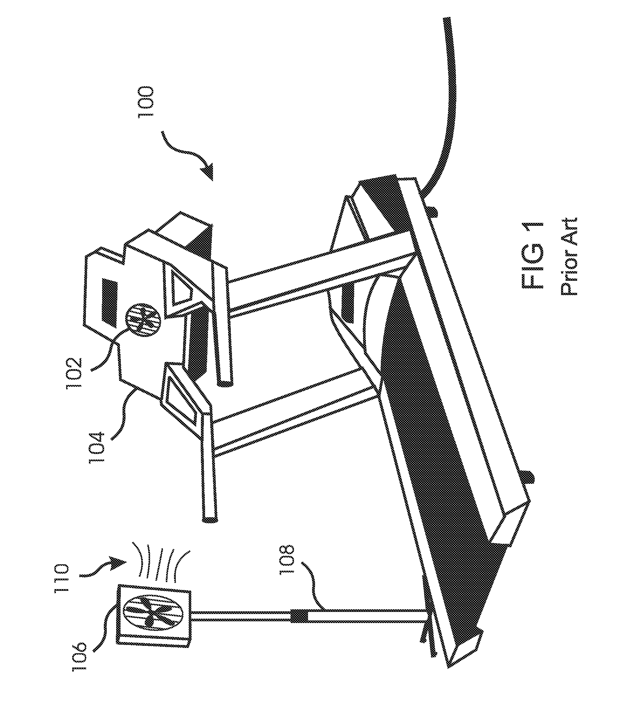
[0044]With reference to FIG. 1, approaches known in the prior art for cooing an exerciser using an exercise machine 100 include cooling fans 102 that are built into a portion 104 of the exercise machine, as well as stand-alone cooling fans 106, mounted for example on floor stands 108, and able to direct a flow of air 110 onto the exerciser. However, a flow of ambient air propelled by a fan provides only limited cooling of an exerciser.

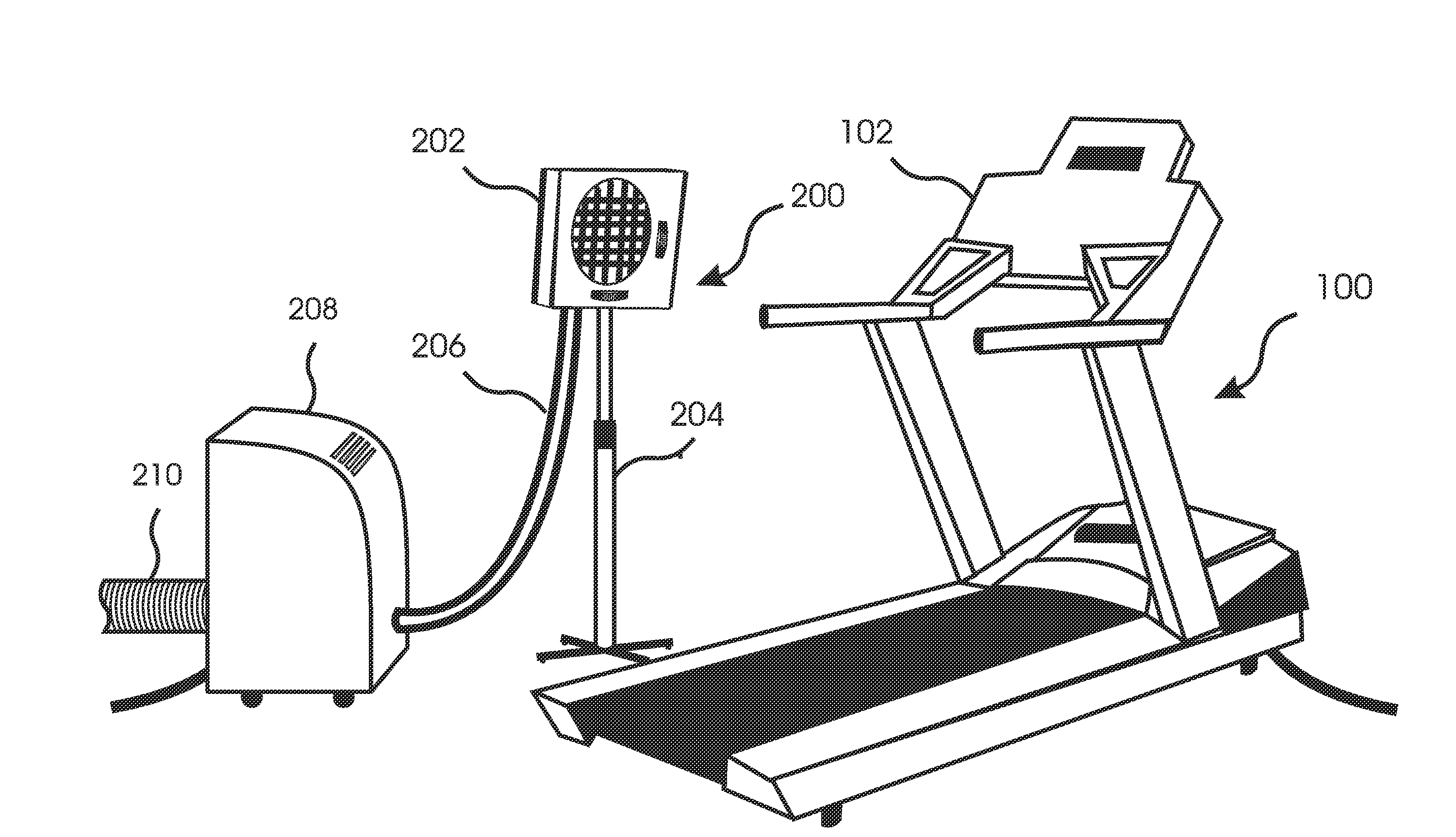
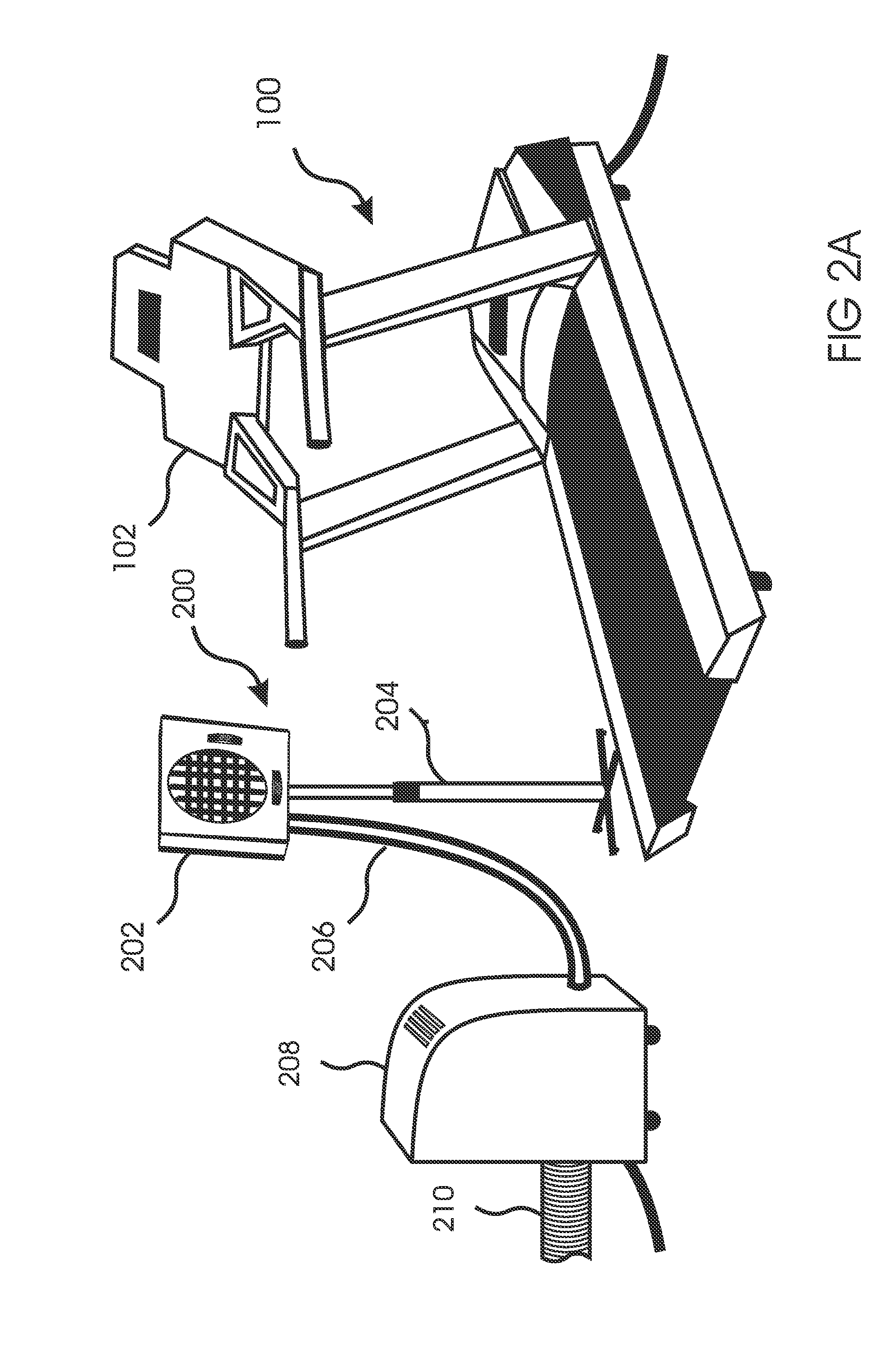
[0045]With reference to FIG. 2A, the present invention 200 includes an airflow director 202 located within a living region of an exercise room that is able to blow chilled air directly onto an exerciser while the exerciser is using an exercise machine 100. In the preferred embodiment of FIG. 2A, the airflow director 202 is supported by a moveable floor stand 204. An air duct 206 is connectable to a source of chilled air 208, which in the embodiment of FIG. 2A is a portable air conditioner. The air duct 206 delivers the chilled air to the airflow direct...


PUM


Abstract

An apparatus is disclosed that cools an exerciser using an exercise machine by blowing chilled air directly onto the exerciser from an airflow director that is independent of the exercise machine. The airflow director is either located within the living space of the exercise room, or able to project a directed stream of chilled air into the living space of the exercise room. The airflow director can include adjustments for chilled air direction, flow rate, and other qualities. The chilled air source can include adjustments for temperature, humidity, and other qualities. A plurality of airflow directors can be included, so as to provide uniform cooing and / or to deliver chilled air to a plurality of exercise machines. A barrier and / or chilled air return vent can be included, so as to save energy and enhance the localization of the chilled air. Some embodiments can also warm the exerciser using warmed air.

Description

FIELD OF THE INVENTION[0001]The invention generally relates to exercise machines, and more specifically to devices for cooling an individual while using an exercise machine.BACKGROUND OF THE INVENTION[0002]Exercise is generally known to have many benefits for individuals of all ages. These benefits include improved cardiovascular health, reduced blood pressure, prevention of bone and muscle loss, maintenance of a healthy weight, improved psychological heath, and many others. However, exercise is generally accompanied by a certain degree of discomfort, including overheating, sweating, fatigue, etc, and this leads to a significant reduction in the amount of exercise undertaken by many individuals, thereby reducing the health benefits derived from exercise.[0003]Because of weather variability, convenience, and time constraints, exercise often takes place indoors using an exercise machine such as a stepper, stationary bicycle, elliptical, treadmill, etc. Attempts are sometimes made to i...

Claims


Application Information

Patent Timeline
Patent Type & Authority Applications(United States)
IPC IPC(8): F24F11/053F24F7/06F24F13/08F24F11/76
CPCA63B22/00A63B2213/00A63B2225/66F24F2221/12F24F13/06F24F2221/08F24F1/025F24F1/022F24F1/04
Inventor GOLDMANN, RICHARDWEINZIMMER, RUSSBURUM, DOUGLAS P.
Owner GOLDMANN RICHARD DR
Why Eureka
Try Eureka