Corrective Device for Deformed Nails

a technology for corrective devices and nails, applied in the field of correction, can solve problems such as pain for patients, difficulty in wearing and releasing nails by themselves, and the end of the corrective device in the width direction of nails is likely to curl and peel, so as to increase the deformation stress and increase the shape memory ability

Active Publication Date: 2010-09-09
FURUKAWA TECHNO MATERIAL
View PDF2 Cites 19 Cited by
  • Summary
  • Abstract
  • Description
  • Claims
  • Application Information

AI Technical Summary

Benefits of technology

[0015]A corrective device for deformed nails corresponding to the second object is the corrective device using as a raw material a cold-rolled plate, a wrought wire rod and the like of a Cu—Al—Mn type shape-memory alloy having a recrystallization texture consisted of a substantially single phase with uniform crystal orientation. The corrective device is provided with a correction plate having a tongue strip protruded from the edge near the nail tip or a protruding part at both ends across the nail width, in which a cold-rolled material is cut out in the rolling direction as the longitudinal direction to form a nearly rectangular metal band with the longitudinal direction being the width direction of a nail. A hooked claw is similarly formed by double-folding of the tongue strip or protruding part as the first corrective device for deformed nails. The width direction of a nail in the correction plate is aligned with the rolling direction of a cold-rolled material, thereby giving shape-memorization ability in relation to the width direction of a nail and increasing the deformation stress in the direction of a nail tip.
[0016]When increasing shape-memorization ability of a Cu—Al—Mn type shape-memory alloy, consequently its correction ability for deformed nails, a hooked claw with a double structure of a folding part and a bending part is formed by folding and bending a tongue strip or protruding part, followed by heat treatment for shape-memorization or super-elasticity to orient the principal direction of a recrystallized β phase to the {112}<110> orientation.

Problems solved by technology

In a method to glue a corrective device to a nail surface, the end of the corrective device in the width direction of a nail is likely to curl and peel.
An adhesive used in wearing may seep between a nail and a corrective device, causing a user tremendous discomfort and an adhesive has to be eliminated from a nail surface after releasing the corrective device, thus causing to avoid use of the adhesion-type corrective device.
In a corrective device, in which tensile force is applied to a hooked end or locking part grappled at the edge across the width of a deformed nail, the hooked end or locking part has to be inserted into the edge across the width of a deformed nail, giving a patient pain, which is a drawback.
A process such as drilling a mounting hole for a locking part in part of the deformed nail and the like is required, depending on a type of the corrective device and is difficult for a patient to wear and release it by himself.
A Cu—Zn type alloy heavily deteriorates with environmental changes, making difficult to wear a corrective device for a long period of time and a Cu—Al—Ni type alloy is extremely brittle and can not be processed to a desired shape of a corrective device.

Method used


Image

  • Corrective Device for Deformed Nails
  • Corrective Device for Deformed Nails
  • Corrective Device for Deformed Nails

Examples


example 1

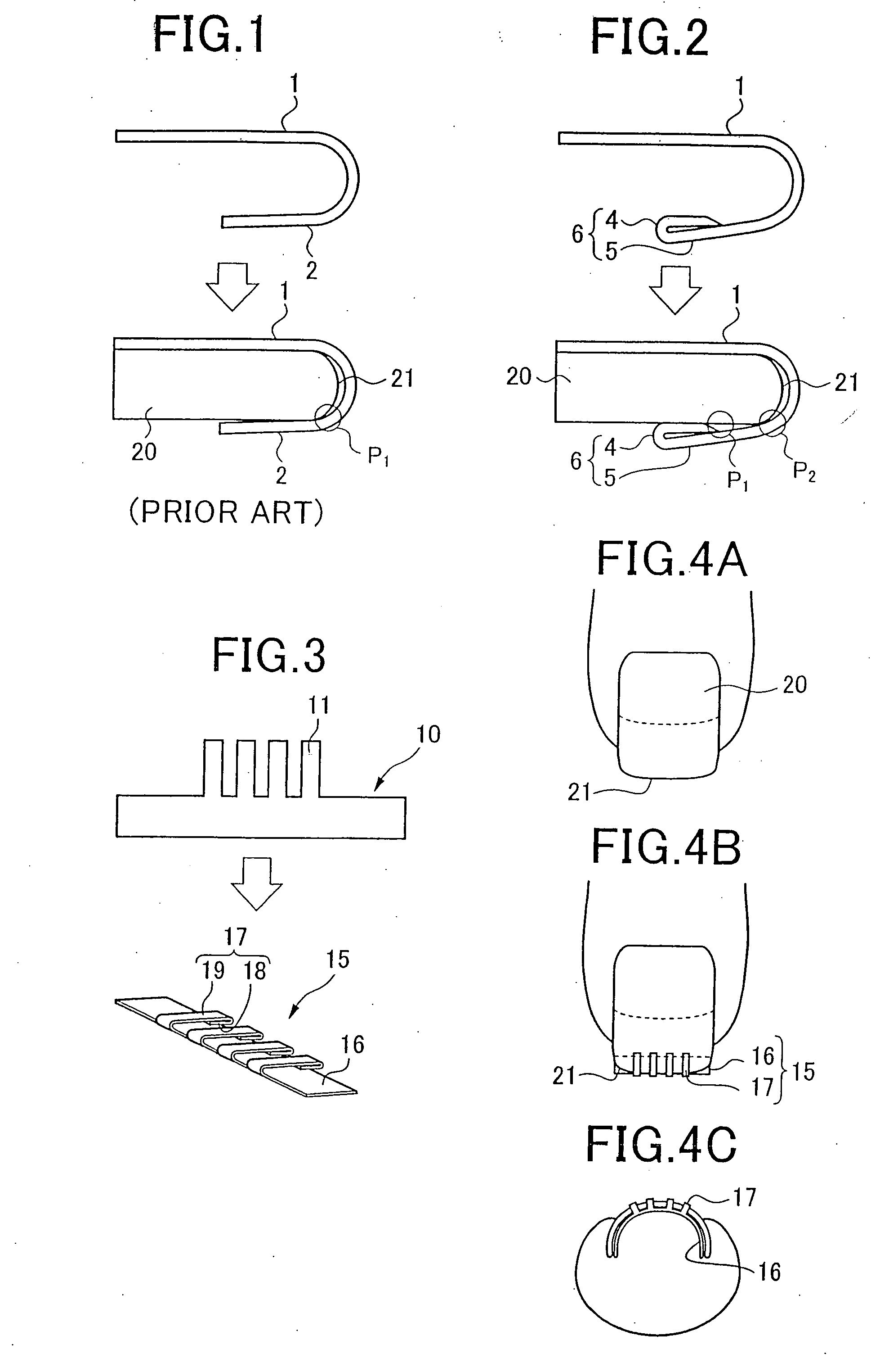
[0048]A hooked claw 6 (FIG. 2) and a nail stopping part 2 of a simple hook (FIG. 1) with length of 3 mm was formed on a short rectangular strip with length of 6.4 mm and width of 2.2 mm cut out from an SUS 304 stainless steel plate with thickness of 0.2 mm in order to compare the effect of a double fold and a simple hook on correction ability for deformed nails and a holding force of a nail. A curvature radius of bending from a corrective plate 1 was made to be approximately 0.475 mm in both the hooked claw 6 and the nail stopping part 2, and a gap between the nail stopping part 2 and the correction plate 1 and a gap between a folding part 4 and the correction plate 4 were chosen to be 0.95 mm, respectively.

[0049]Using an aluminum plate with plate thickness of 1.02 mm as a virtual nail, the edge of the aluminum plate was sandwiched between a correction plate 1 and a hooked claw 6 or between a correction plate 1 and a nail stopping part 2, respectively, to measure a load of pulling o...

example 2

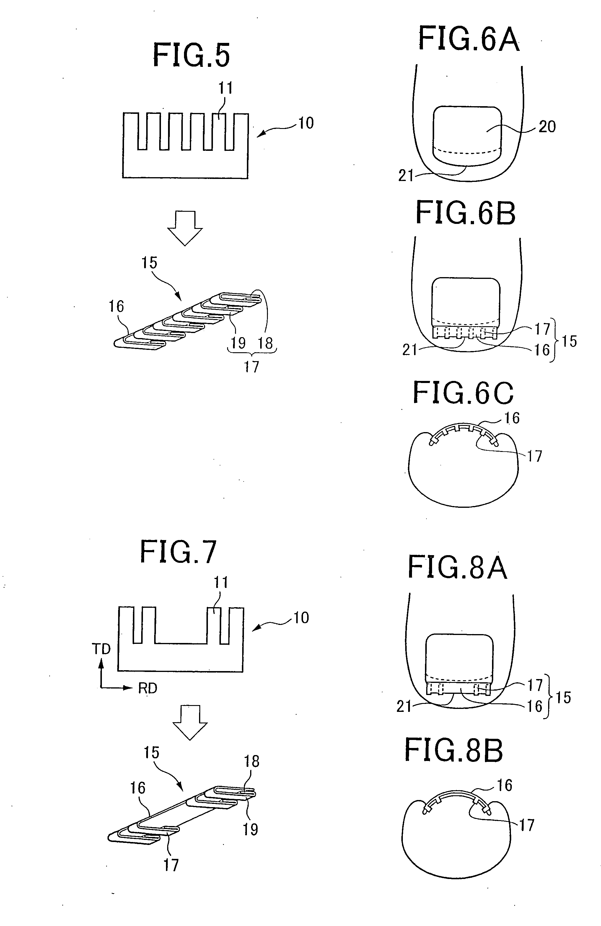
[0063]A SUS 304 stainless steel cold-rolled steel plate with thickness of 0.8 mm was punched out to collect an elastic metal strip 10 (FIG. 3) with four tongue strips 11 with width of 1.5 mm and length of 5 mm protruded from the one edge of a correction plate 16 with a size of 22 mm×3 mm. After the tip of tongue strip 11 was bent, the tongue strip 11 was further bent at the location 1 mm from the end of the correction plate 16 to form a hooked claw 17 with a double structure of a folding part 18 and a bending part 19.

[0064]The product was next heat-treated in a red hot condition at 500° C. for 30 minutes, followed by water hardening to remove stress and strain introduced in the bending process as well as improve hardness, consequently elasticity of a corrective device 15.

[0065]A manufactured corrective device for a deformed nail 15, was applied to ten subjects to investigate the progress of correcting ingrown nails. A degree of correction was varied with subjects, but the effect of ...

example 3

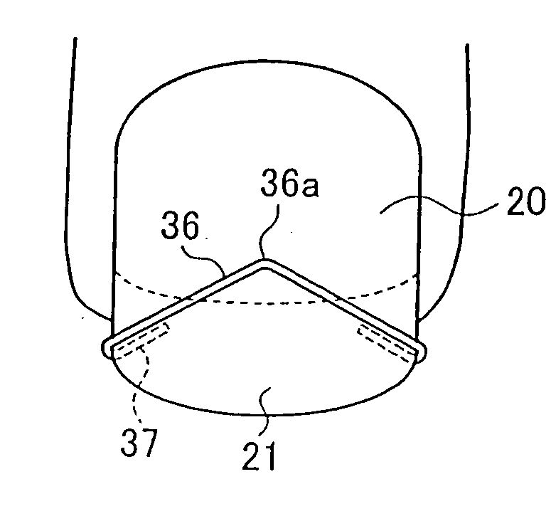
[0071]A SUS 304 stainless steel cold-draw wire rod with wire diameter of 0.7 mm was cold-rolled to thickness of 0.4 mm to collect a wrought wire rod with length of 28 mm. Both ends of a correction part 36 were bent, followed by further bending at a location 2 mm from the tip of the fold to form a hooked claw 37 with a double structure of a folding part 38 and a bending part 39, which was finally bent in a dogleg shape with an open angle of 120 degrees, forming the shape in FIG. 10. The product after processing was heat-treated in a red hot condition at 500° C. for 30 minutes, followed by water hardening to remove stress and strain introduced in the bending process, as well as to improve hardness and consequently elasticity of a corrective device 35.

[0072]A manufactured corrective device for a deformed nail 35 was applied to ten subjects to investigate the progress of correcting ingrown nails. A degree of correction was varied with subjects, but the effect of correction was observed ...


PUM

PropertyMeasurementUnit
thicknessaaaaaaaaaa
widthaaaaaaaaaa
lengthaaaaaaaaaa

Abstract

An elastic metal strip 10 aligning the longitudinal direction with the rolling direction of a cold-rolled plate is collected and processed to a shape comprising a correction plate 16 with the longitudinal direction of the elastic metal 10 as the width direction of nail and a plurality of tongue strips 11 protruded from the edge of the correction plate 16 near the nail tip. The tongue strip 11 is folded and bent to form a hooked claw 17 with a double structure of a folding part 18 and a bending part 19. A nail tip 21 of a deformed nail 20 is inserted between the hooked claw 17 and the correction plate 16 to apply a restoring force of elasticity in the correction plate to the deformed nail 20 as correction ability for deformed nails. A wrought wire rod can be used instead of a cold-rolled plate and a Cu—Al—Mn type shape-memory alloy may further be used as a raw material.

Description

FIELD OF THE INVENTION[0001]The present invention relates to a corrective device readily worn on deformed nails such as ingrown nails, ingrown toenails and the like and used for eliminating deformation and manufacture method thereof.RELATED ART[0002]Various corrective devices for deformed nails have been conventionally proposed to correct ingrown nails, ingrown toenails and the like. For example, there is a corrective device for ingrown nails, gluing a small strip with an appropriate restoring force onto a surface of an ingrown nail, gradually correcting ingrown nails to normal configuration (Patent Document 1), a corrective device for ingrown nails of providing an elastic force to a pair of hooked ends of the device grappled at the edge across the width of the deformed nail to pull (Patent Document 2), a corrective device of applying a tensile force in the direction opposite to the deformation direction to both edges of a nail (Patent Document 3) and the like.[0003]A corrective dev...

Claims


Application Information

Patent Timeline
Patent Type & Authority Applications(United States)
IPC IPC(8): A61F5/11B21D31/00
CPCA61F5/11
Inventor ISHIDA, KIYOHITOYAMAUCHI, KIYOSHIKAINUMA, RYOSUKESUTOU, YUJIOMORI, TOSHIHIROOGAWA, AKIRA
Owner FURUKAWA TECHNO MATERIAL
Why Eureka
Try Eureka