Eureka AIR delivers breakthrough ideas for toughest innovation challenges, trusted by R&D personnel around the world.

Anti-seeding arrangement

a technology of anti-seeding and anti-seeding, which is applied in the field of anti-seeding arrangement, can solve the problems of thermal destruction and/or denaturation of said tissue, excessive surgery, and considerable hospitalisation

Active Publication Date: 2010-09-09
NEODYNAMICS AB
View PDF12 Cites 5 Cited by
  • Summary
  • Abstract
  • Description
  • Claims
  • Application Information

AI Technical Summary

Benefits of technology

[0051]This aspect of the present invention is advantageous since the impedance being an electrical quantity that is easily obtainable and convenient to utilize in electrical or electronic control means.
[0080]Application of sensing means for the detection of movement of the elongated hollow member together with the usage of radio frequency power creating an essentially instantaneous denaturation of tissue surrounding an anti-seeding electrode, provides a rapid arrangement for anti-seeding without being directed towards time consuming alternatives as presented by the prior art. The invention is also advantageous since the rapid response will be dependent on the triggering of the electromagnetic field generator.

Problems solved by technology

For such cancer tumours, having an extension that typically is less than 10 mm, conventional surgery may be seen as too coarse a method.
The goal of radical mastectomy is to remove all malignant tissue, which combined with lymph node resection, often results in considerable hospitalisation.
The high current density at the needle generates heat in the tissue, causing thermal destruction and / or denaturation of said tissue.
In addition, said techniques and methods may also touch or puncture local infections.
Upon penetration or contacting by the distal end of malignant tissue, said distal end becomes contaminated with non-healthy cells.
Tumour seeding may thus be result of core biopsy, laparoscopy, radio frequency ablation, injection, and fine needle aspiration or punctuation etc. and can therefore negate the benefits of the operation involved.
One disadvantageous property of this technique is that the delivered radio frequency energy heats the tissue surrounding the track such that tissue of a relatively large depth is affected by the high temperature produced.
Another disadvantage of the diagnostic equipment of this technique is that sample tissue in the needle is also affected by the heating caused by the radio frequency energy.
A potential disadvantage of the technique of US 2004 / 0186422 A1 is associated with the application of the short bursts or continuous radio frequency energy to substantially seal the track when the needle or instrument is being retracted.
Since the technique is operated manually and the needle is typically held and retracted by an operator, there is a risk that viable cells will remain in the track after the application of the radio frequency energy when retracting the needle, since the result of treating the tract is dependent of the skill of the operator using this technique.
Another potential disadvantage with the regime of US 2004 / 0186422 A1 is there is no solution to disruption of tumour cells when the inserted instrument penetrates through the tumour, potentially leading to seeding of tumour cells.
In addition, since the technique is operated manually, the technique is time consuming in general and consumes time for an operator in particular, which are disadvantageous.
A clear disadvantage with the technique as disclosed by US 2003 / 0195500 is that this device uses microwave frequency energy.
A consequence of using microwave frequencies is that a comparatively large tissue region is heated, where said region also comprises healthy tissue in no need of treatment, which clearly is non-beneficial.
Another disadvantage of the US 2003 / 0195500 technique is that coagulation of the entire track requires multiple applications of micro-wave energy, where the delivery needle is rejected piece-wise, and where microwave frequencies are applied to the delivery needle in between the rejections, due to the fact that each application of the microwave energy of the power being used to achieve the isotherms as mentioned above, lasts a relatively long time.
Moreover, manual operation of this regime brings the disadvantage of risking that viable cells remain in the track subsequent to the application of micro-wave energy, since the tissue surrounding the track is often non-homogenous and therefore require different applications of energy to ablate the track.
Yet another disadvantage is that energy absorption upon application of microwave frequency is often non-homogenous, which can result in spots being over-heated, so called “hot spots”.
By generating radio frequency energy, the cannula is heated above a critical temperature causing the tissue surrounding the cannula to become non-viable.
One drawback with the biopsy needle technique as disclosed in U.S. Pat. No. 6,126,216 is the application of radio frequency energy which is applied to achieve elevated temperature in tissue of a depth of approximately 10 cell layers.
Using a low current density however requires a long duration of application of the radio frequency energy, which for this reason is a clear drawback since the rise in temperature during that duration will be influenced by heat conduction to neighbouring tissues and thereby also by blood perfusion and other tissue properties.
Another drawback of the technique as disclosed by U.S. Pat. No. 6,126,216 is the skin burn effect that is caused due to the contact between the electrode and the skin upon penetrating the skin by the biopsy needle, upon application of radio frequency energy to the biopsy needle.
The usage of the entire shaft of the needle as an electrode thus results in undesired skin burn effects.
A potential drawback of the technique of U.S. Pat. No. 6,126,216 is that full penetration of a tumour by the electrode may result in dislocated viable tumour cells that could proliferate in healthy tissue into new cancer tumours.
Conclusively, a common disadvantage of the prior art techniques and disclosures is that movement of inserted instruments in longitudinal directions may result in non-complete track tumour cell killing.
In addition, continuous application of energy may result in an unnecessarily large diameter of tissue killing that the sample in the needle is affected as well as an increased operation time.

Method used


Image

  • Anti-seeding arrangement
  • Anti-seeding arrangement

Examples


Embodiment Construction

[0084]The present invention thus relates to an arrangement for treating a human or animal body in general, and to an arrangement for denaturating tissue, cells and infectious matter in a human or animal body in particular.

[0085]Since seeding or spreading of malignant cells, tissue or infectious matter is an evident risk when inserting medical equipment into a human or animal body site containing such matter, seeding may occur in various applications such as infusion, radio frequency ablation, fine needle aspiration, core biopsy as well as endoscopic procedures. For this reason and to enable a more efficient anti-seeding procedure the anti-seeding arrangement of the present invention is arranged to be utilized in every one of the applications as mentioned above, that is in infusion, in radio frequency ablation, in fine needle aspiration, in core biopsy as well as in endoscopic procedures.

[0086]Whenever a member is passed through healthy tissue after the management of infectious or ma...


PUM


Abstract

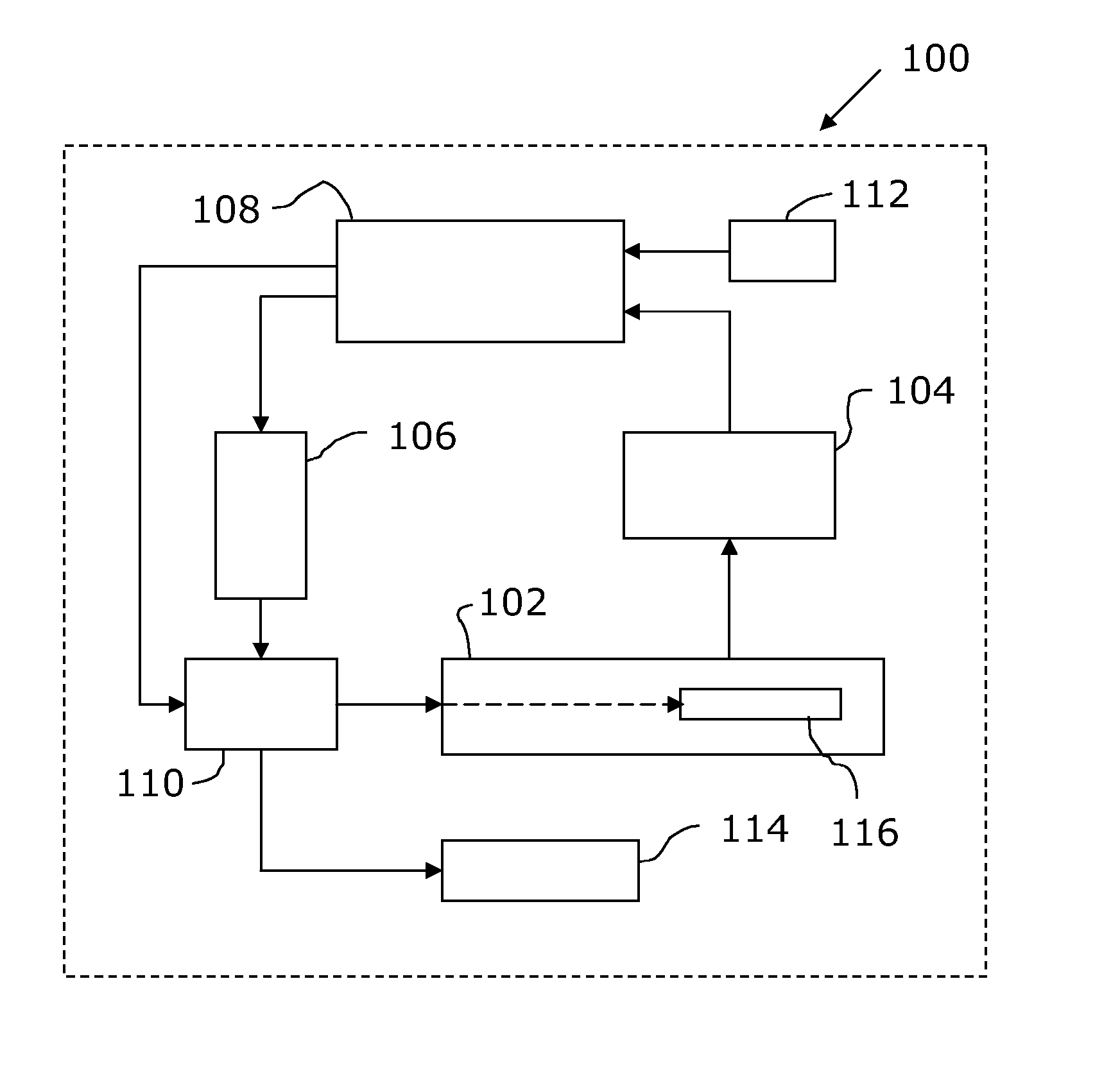
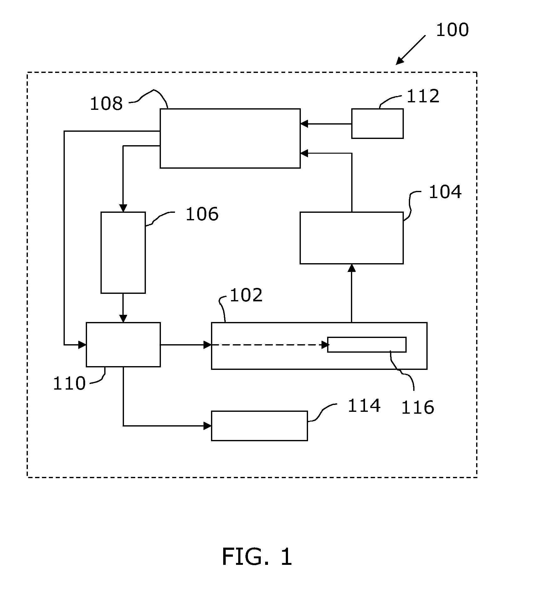
The present invention relates to an anti-seeding arrangement (100) for invasive treatment of a human or animal body comprising an elongated hollow member (102), and a first electrode (116) of which one portion is arranged near one end of the elongated hollow member (102), said first electrode (116) being connectable to an electromagnetic field generator (110), wherein the elongated hollow member (102) is arranged to be inserted into the human or animal body, control means (106, 108) arranged to control the electromagnetic field generator (110) for delivering radio frequency bursts to the first electrode (116), and sensing means (104) to sense a physical property dependent on the insertion length of the elongated hollow member (102) in the human or animal body, and wherein the control means (106, 108) is arranged to control the operation of the electromagnetic field generator (110) in dependence of the sensed physical property.

Description

[0001]The present invention relates in general to providing an arrangement for invasive operations in human or animal bodies, and especially to providing an arrangement for anti-seeding in connection to invasive operations in human or animal bodies.DESCRIPTION OF RELATED ART[0002]Many people in the western world face the prospect of cancer. The most common cancer forms in females and males are breast cancer and prostatic cancer, respectively.[0003]A successful cancer therapy is often dependent on a high quality tumour diagnosis. There are today two major methods of morphological diagnosis. These are histopathological examination of surgical biopsies or core biopsies and cytopathological examination of fine needle aspirates.[0004]In core biopsy, a tissue sample is removed from the lesion, for example by using a coarse core biopsy needle. This tissue sample is then examined histologically.[0005]In cytological diagnosis, a suspension of cells is aspirated from the lesion with the aid o...

Claims


Application Information

Patent Timeline
Patent Type & Authority Applications(United States)
IPC IPC(8): A61B18/18
CPCA61B10/0233A61B18/1206A61B18/1477A61B19/5244A61B2018/1467A61B2018/0019A61B2018/00196A61B2018/00875A61B2018/00083A61B34/20
Inventor WIKSELL, HANSAUER, GERTEKSTRAND, VILHELM
Owner NEODYNAMICS AB
Why Eureka
Eureka Blog
Learn More