
Particulate matter detection device

a detection device and particle technology, applied in measurement devices, scientific instruments, instruments, etc., can solve the problems of air pollution, adversely affecting the environment, and increase the amount of particulate matter in the exhaust gas discharged to atmospheric air, so as to reduce the amount of discharged particulate matter, reduce the measurement error, and prevent air pollution

Inactive Publication Date: 2010-09-16
NGK INSULATORS LTD
View PDF4 Cites 27 Cited by
  • Summary
  • Abstract
  • Description
  • Claims
  • Application Information

AI Technical Summary

Benefits of technology

The present invention provides a particulate matter detection device that can easily detect the amount and concentration of particulate matter in a gas flow. The device includes a first electrode and a second electrode with a space between them, where the gas containing particulate matter flows. The device also includes a protective film with a specific volume resistivity that prevents corrosion and allows the electrical recognition of low-resistance particulate matter. The device can measure the electric properties of the particulate matter, such as resistance, inductance, capacitance, and impedance, to determine the amount and concentration of the particulate matter. The device is cost-effective and can provide accurate results with minimal measurement error.

Problems solved by technology

An exhaust gas from a diesel engine or the like includes a particulate matter ((PM) detected as three components of an organic solvent soluble component, soot and sulfate), and this particulate matter has been a cause for air pollution.
In particular, when a defect occurs in a particulate matter generation source such as the diesel engine, the particulate matter in the exhaust gas discharged to atmospheric air increases, and noticeably adversely affects the environment.
However, it cannot be considered that there is not any possibility of the occurrence of a defect such as cracking due to heat deterioration or the like.
If there is such a possibility, the particulate matter leaks though its amount is small.
However, in the method described in Patent Document 1, the ion current for charging the particulate matter is weak, whereby a large-scale detection circuit for detecting the weak ion current is required, and the device becomes expensive.
There has also been a problem that electrodes and the like are corroded by acid or alkali in the exhaust gas.

Method used


Image

  • Particulate matter detection device
  • Particulate matter detection device

Examples


example 1

Preparation of Forming Material

[0085]Alumina was used as a ceramic material, polyvinyl butyral was used as a binder, di-2-ethylhexyl phthalate was used as a plasticizer, sorbitan trioleate was used as a dispersant, and an organic solvent (xylene:butanol=6:4 (mass ratio)) was used as a dispersion medium. These materials were placed and mixed in an alumina pot, to prepare a slurry-like forming material for preparing a green sheet. As to the used amounts of the materials, with respect to 100 parts by mass of alumina, 7 parts by mass of binder, 3.5 parts by mass of plasticizer, 1.5 parts by mass of dispersant and 100 parts by mass of organic solvent were used.

[0086]Next, the obtained slurry-like forming material for preparing the green sheet was stirred under a reduced pressure, defoamed and prepared so as to have a viscosity of 4 Pa·s. The viscosity of the slurry was measured by a B-type viscosity meter.

[0087](Formation Processing)

[0088]Next, the slurry-like forming material obtained b...

example 2

[0099]A particulate matter detection device was prepared in the same manner as in Example 1 except that a protective film was what was doped with a metal. The protective film doped with the metal was prepared as follows. The preparation method of the protective film was similar to that of Example 1, but silica and titania were used as the materials of the protective film, and a blend ratio of titania (TiO2) with respect to base silica (SiO2) in terms of Ti atoms was 5 mol %. The volume resistivity of the protective film was 108 Ωcm. In the same manner as in Example 1, sensitivity measurement and corrosion test were performed. Results are shown in Table 1.

example 3

[0100]A particulate matter detection device was prepared in the same manner as in Example 1 except that a protective film was formed of two layers of an insulating protective film and a low resistance film. The protective film formed of the two layers of the insulating protective film and the low resistance film was prepared as follows. The insulating protective film was formed by screen printing on the surface of a portion of a green laminate on which measurement electrodes 5, 15 were printed, and the green laminate was dried and fired in the same manner as in Example 1, followed by forming the low resistance film on the surface of the insulating protective film by CVD. The screen printing was performed by using trade name TSU4060 manufactured by Seritech Co. Moreover, the CVD was performed by using trade name Super 7 manufactured by Universal Technics Co., Ltd. The material of the insulating protective film was silica, and the material of the low resistance film was diamond-like c...


PUM

PropertyMeasurementUnit
volume resistivityaaaaaaaaaa

Abstract

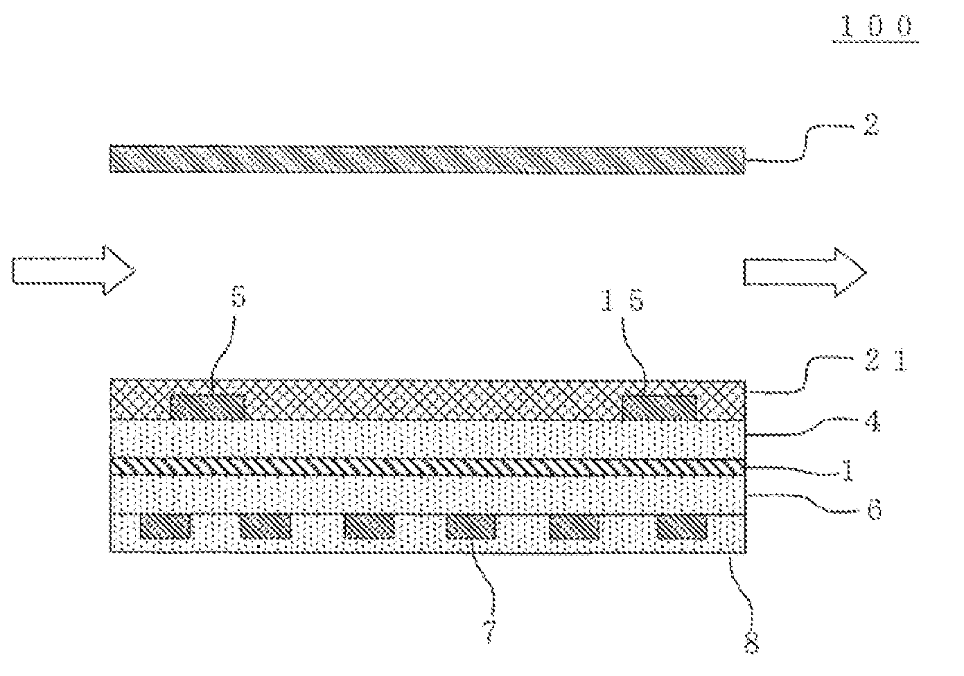
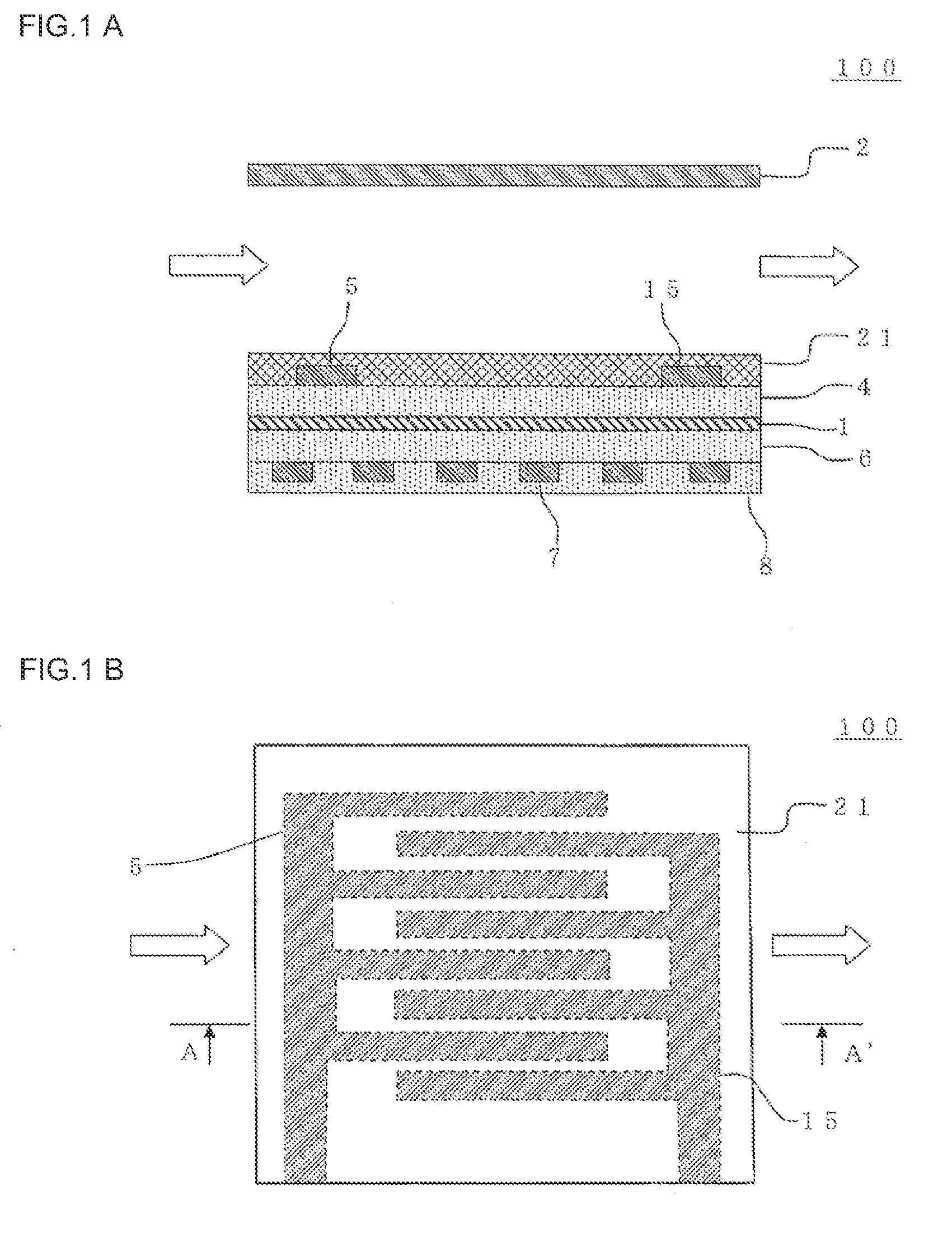
A particulate matter detection device 100 includes a first electrode 1 and having one surface covered with a dielectric material; a second electrode 2 which is disposed on the side of the one surface of the first electrode 1 via a space where a gas including a particulate matter flows and which performs one or both of the formation of discharge and an electric field by a voltage applied between the first electrode 1 and the second electrode; a pair of measurement electrodes 5, 15 disposed on the surface of the dielectric material so as to face each other; and a protective film 21 disposed on the surfaces of the pair of measurement electrodes and having a volume resistivity of 10 Ωcm to 1012 Ωcm, and the variate of electric properties between the pair of measurement electrodes is measured, whereby the amount of the collected particulate matter can be obtained.

Description

BACKGROUND OF THE INVENTION[0001]1. Field of the Invention[0002]The present invention relates to a device which detects a particulate matter included in an exhaust gas from a diesel engine or the like.[0003]2. Description of the Related Art[0004]An exhaust gas from a diesel engine or the like includes a particulate matter ((PM) detected as three components of an organic solvent soluble component, soot and sulfate), and this particulate matter has been a cause for air pollution. In particular, when a defect occurs in a particulate matter generation source such as the diesel engine, the particulate matter in the exhaust gas discharged to atmospheric air increases, and noticeably adversely affects the environment. To prevent this problem, it is essential to detect the particulate matter in the exhaust gas and to recognize the defect in the diesel engine or the like.[0005]Moreover, in recent years, to prevent the pollution and improve the environment, a diesel particulate filter (DPF) h...

Claims


Application Information

Patent Timeline
Patent Type & Authority Applications(United States)
IPC IPC(8): G01N37/00
CPCG01N27/68G01N15/0656
Inventor EGAMI, TAKASHISAKUMA, TAKESHITOKUDA, MASAHIROKONDO, ATSUO
Owner NGK INSULATORS LTD
Learn More