Ferrous-Metal-Alkaline-Earth-Metal Silicate Mixed Crystal Phosphor and Light Emitting Device using The Same

a technology of earth metal silicate and mixed crystal phosphor, which is applied in the direction of discharge tube luminescnet screens, sustainable buildings, energy-saving lighting, etc., can solve the problems of limited use of sulphides, leakage of stability over the burning time, and strict dry conditions, etc., to achieve less negative electrochemical potential, increase water stability, and good conversion properties

Inactive Publication Date: 2010-09-16
MERCK PATENT GMBH +1
View PDF17 Cites 20 Cited by
  • Summary
  • Abstract
  • Description
  • Claims
  • Application Information

AI Technical Summary

Benefits of technology

[0054]Owing to sensitivity to protonic solvents of general Alkaline Earth silicate based phosphors, Iron group elements, when incorporated into the lattice, increase the stability to water strongly which is caused by the less negative electrochemical potentials of Iron, Cobalt and Nickel compared to Alkaline

Problems solved by technology

Furthermore Garnets are only excitable by blue light and therefore their use is limited to applications based on blue semiconductor chips.
As additional phosphors some inorganic sulphide phosphors (e.g. (Ca, Sr) S:Eu) can be used

Method used


Image

  • Ferrous-Metal-Alkaline-Earth-Metal Silicate Mixed Crystal Phosphor and Light Emitting Device using The Same
  • Ferrous-Metal-Alkaline-Earth-Metal Silicate Mixed Crystal Phosphor and Light Emitting Device using The Same
  • Ferrous-Metal-Alkaline-Earth-Metal Silicate Mixed Crystal Phosphor and Light Emitting Device using The Same

Examples


first embodiment

[0067]Some of the new luminous materials according to the invention are shown in table 1. Luminescence data are compared to pure Alkaline Earth Silicates doped with Rare Earth elements.

TABLE 1Relative optical propertiesEmissionmaximumFe, Cowithout Fe,and / or NiLuminousCo and / orcontainingComposition of Ferrous metal containing SilicatesintensityNiSilicates(Ba0.177Sr0.799Ca0.001Fe0.003Eu0.02)2SiO4100.8%565.0 nm563.0 nm(Ba0.3525Sr0.625Co0.0025Eu0.02)2SiO499.7%533.0 nm531.5 nm(Ba0.222Sr0.7455Ni0.0025Eu0.03)2SiO4100.2%560.0 nm557.5 nm(Ba0.897Sr0.05Fe0.05Eu0.003)2Si(Al0.0001)O4.00015101.7%508.5 nm507.0 nm(Ba0.97Eu0.03)3(Mg0.9Fe0.1)Si2O8100.5%437.0 nm436.5 nm(Ba0.95Sr0.02Eu0.03)3(Mg0.9475Fe0.05Co0.0025)(Si0.99Ge0.01)2O8100.5%437.5 nm437.0 nm(Ba0.67Sr0.31Eu0.02)3(Mg0.81Fe0.07Mn0.12)Si2O8101.3%639.5 nm643.0 nm(Ba0.919Fe0.03Ni0.001Eu0.05Dy0.0002)(Si0.98Ge0.02)2O5.0003102.1%521.0 nm519.5 nm(Ba0.0015Sr0.951Ca0.001Fe0.015Ni0.0015Eu0.03)3SiO5100.7%575.0 nm572.5 nm(Ba0.96Eu0.04)2(Mg0.82Fe0.08Zn0.1)...

second embodiment

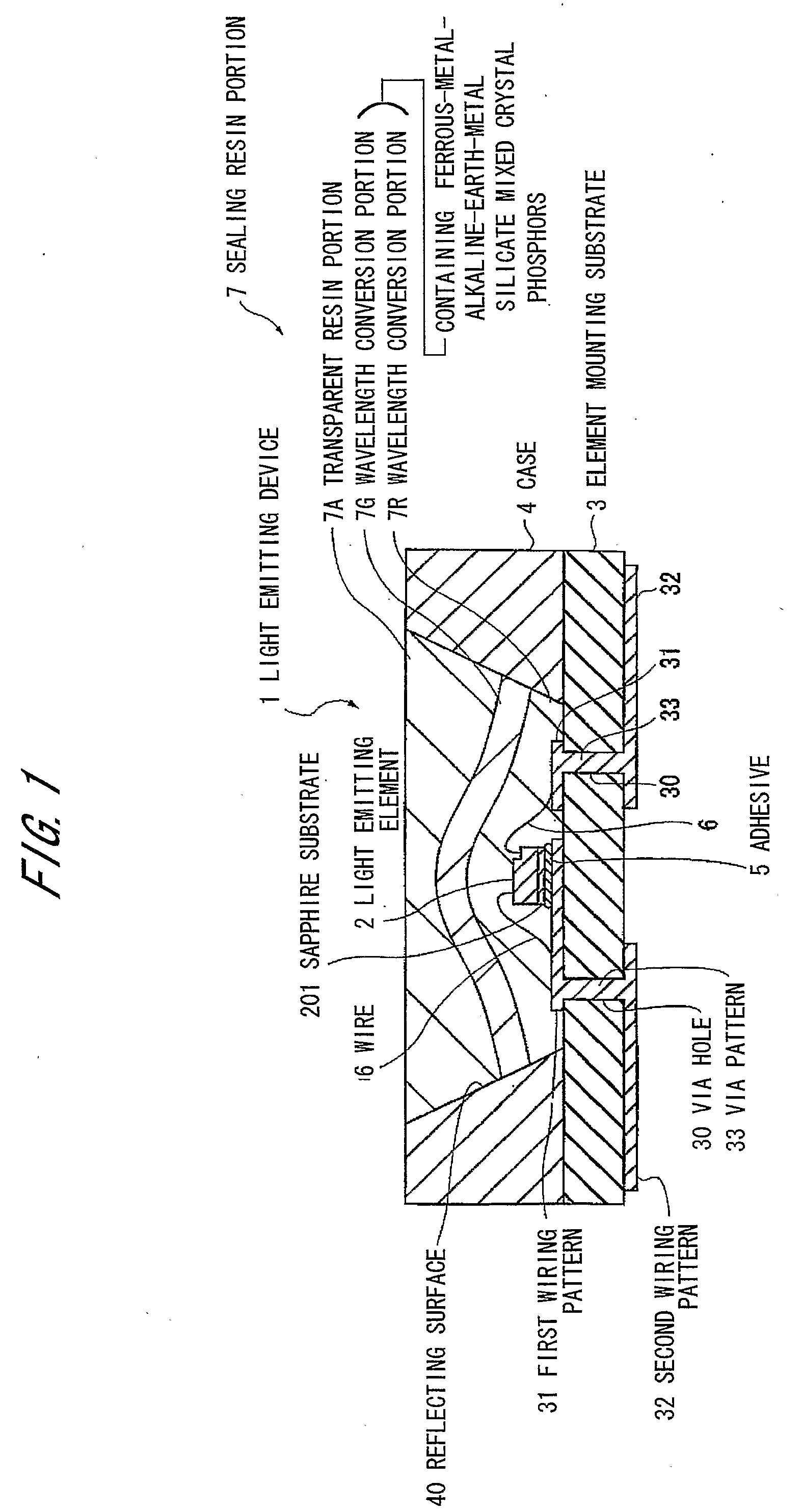
[0081]FIG. 1 is a cross-sectional view showing a light emitting device of the second preferred embodiment according to the invention.

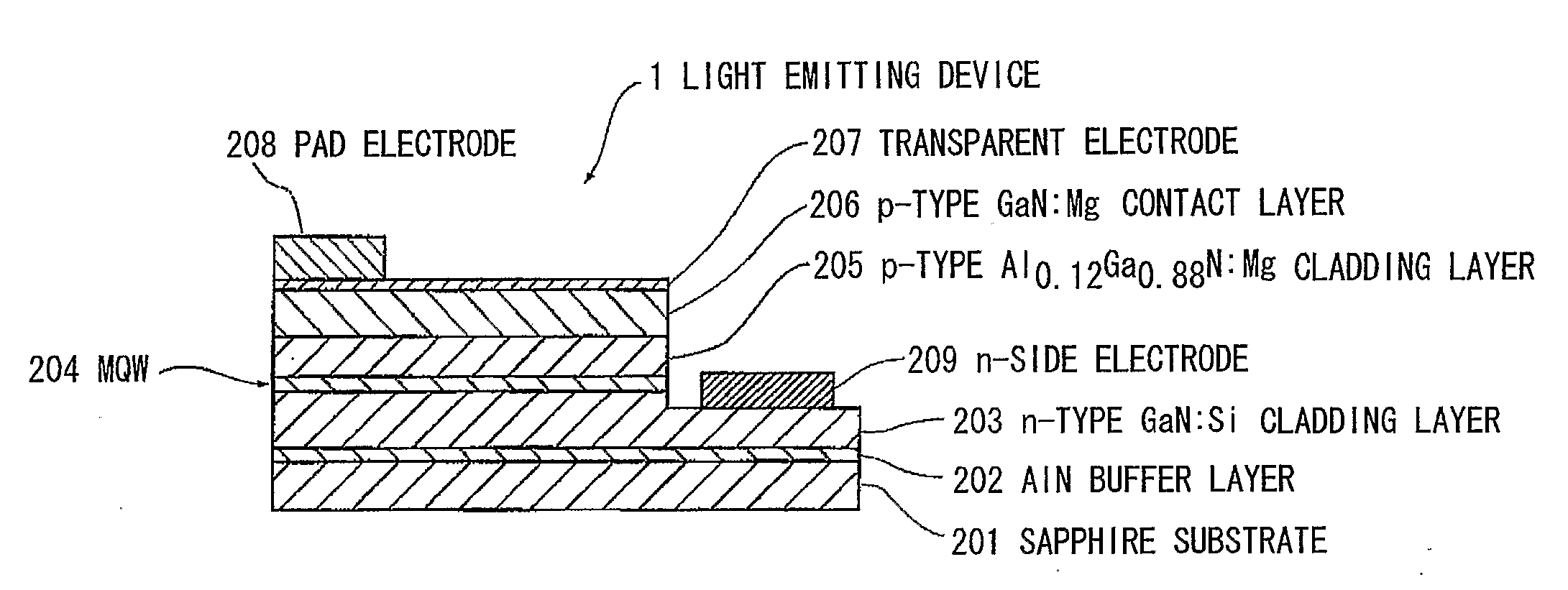
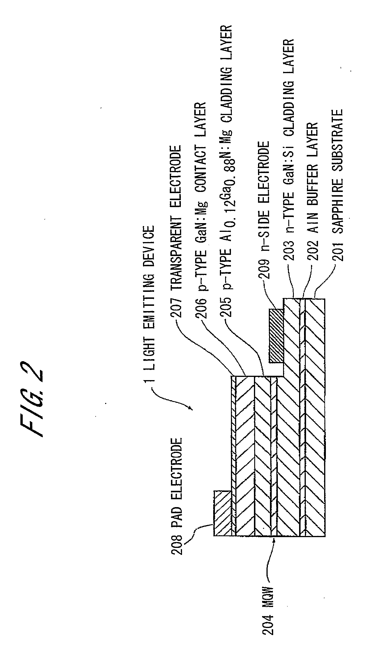
[0082]The light emitting device 1 comprises a light emitting element 2 comprising semiconductor layers (GaN-type semiconductor layers) comprising nitride based semiconductor compounds as a light emitting portion, a element mounting substrate 3 mounting the light emitting element 2 thereon and electrically connected to outside, a case 4 formed integrally with the element mounting substrate 3, comprising a reflecting surface 40 with a slope in the inner surface, an adhesive 5 fixing the light emitting element 2 on the element mounting substrate 3, a wire 6 comprising Au, electrically connecting electrodes of the light emitting element 2 and a first wiring pattern 31 formed on the element mounting substrate 3 as an electrical power supply, and a sealing resin portion 7 comprising a wavelength conversion portion 7R sealing the light emitting element 2 fixe...

third embodiment

[0101]FIG. 3 is a cross-sectional view showing a light emitting device of the third preferred embodiment according to the invention. In the explanation described below, as to the same structural and functional portions as in the second preferred embodiment, the same references are used.

[0102]The light emitting device 1 is different from the device of the second preferred embodiment in that the device 1 comprises an emission path formed by that an emission pattern 34A is formed just below the light emitting element 2 explained in the second preferred embodiment with an electrically conductive paste, and the emission pattern 34A is connected to an emission pattern 34B formed in the back surface side of the substrate through the via patterns 33.

Advantages of the Third Embodiment

[0103]According to the third preferred embodiment described above, in addition to the preferred advantages of the second preferred embodiment, heat caused by the emission of the light emitting element 2 is condu...


PUM


Abstract

A ferrous-metal-alkaline-earth-metal mixed silicate based phosphor is used in form of a single component or a mixture as a light converter for a primarily visible and/or ultraviolet light emitting device. The phosphor has a rare earth element as an activator. The rare earth element is europium (Eu). Alternatively, the phosphor may have a coactivator formed of a rare earth element and at least one of Mn, Bi, Sn, and Sb.

Description

TECHNICAL FIELD[0001]The invention relates to a ferrous-metal-alkaline-earth-metal silicate mixed crystal phosphor, which is doped with a rare earth element as an activator, to be available as a light converter for near-ultraviolet and visible light sources, and to a light emitting device using the phosphor.[0002]The present application is based on Japanese patent application No. 2006-086314 filed on Mar. 27, 2006, the entire contents of which are incorporated herein by reference.BACKGROUND ART[0003]Luminescent materials to emit green, yellow or red light under excitation with near-ultraviolet or blue light became more and more important over the last few years. The main reason for this is the possibility of using them in light emitting devices as color converters for the production of white light. The most common principle is to use a blue light emitting device with a yellow color converter. The resulting light is white with a relatively low color rendering index. Especially the Ce...

Claims


Application Information

Patent Timeline
IPC IPC(8): H01L33/50C09K11/59C09K11/54C09K11/67C09K11/81C09K11/85C09K11/84H01L33/32H01L33/62
CPCC09K11/7734C09K11/7792H01J1/63H01L33/502H01L33/504Y02B20/181H01L2224/73265H01L2224/48091H01L2224/48227H01L2924/00014Y02B20/00C09K11/77342C09K11/77922C09K11/77344H01L33/00
Inventor INOUE, MITSUHIRONAMIKI, AKIOISHIDA, MAKOTONONOGAWA, TAKASHIOTA, KOICHIHIRANO, ATSUOTEWS, WALTERROTH, GUNDULATEWS, STEFAN
Owner MERCK PATENT GMBH
Why Eureka
Try Eureka