LED power-source circuit and illumination fixture using the same

a technology of led power supply circuit and lamp fixture, which is applied in the direction of electric variable regulation, process and machine control, instruments, etc., can solve the problems of increasing the number of led lamp fixtures, increasing the voltage of the noise terminal, and reducing the ability of the circuit to tolerate a surge voltage (common mode). the effect of reducing the ability of the circuit to tolerate a surge voltag

Active Publication Date: 2010-09-16
PANASONIC CORP
View PDF9 Cites 15 Cited by
  • Summary
  • Abstract
  • Description
  • Claims
  • Application Information

AI Technical Summary

Benefits of technology

[0008]In an LED power-source circuit having a DC-DC conversion circuit, a noise filter needs to be provided so that a switching noise is not leaked into an input power-source line. Conventionally, noise terminal voltage in an LED lamp fixture tends to increase because of an increase in the number of LEDs. For purpose of noise reduction, a circuit ground of the DC-DC conversion circuit is connected to a lamp fixture ground. However, if the capacitance between the circuit ground and the fixture increases, the ability of the circuit tolerate a surge voltage (common mode) decreases. At the same time, the capacitance has to be selected so as to suppress the noise terminal voltage within a controlled range and simultaneously satisfy surge performance.

Problems solved by technology

Conventionally, noise terminal voltage in an LED lamp fixture tends to increase because of an increase in the number of LEDs.
However, if the capacitance between the circuit ground and the fixture increases, the ability of the circuit tolerate a surge voltage (common mode) decreases.

Method used


Image

  • LED power-source circuit and illumination fixture using the same
  • LED power-source circuit and illumination fixture using the same
  • LED power-source circuit and illumination fixture using the same

Examples


first embodiment

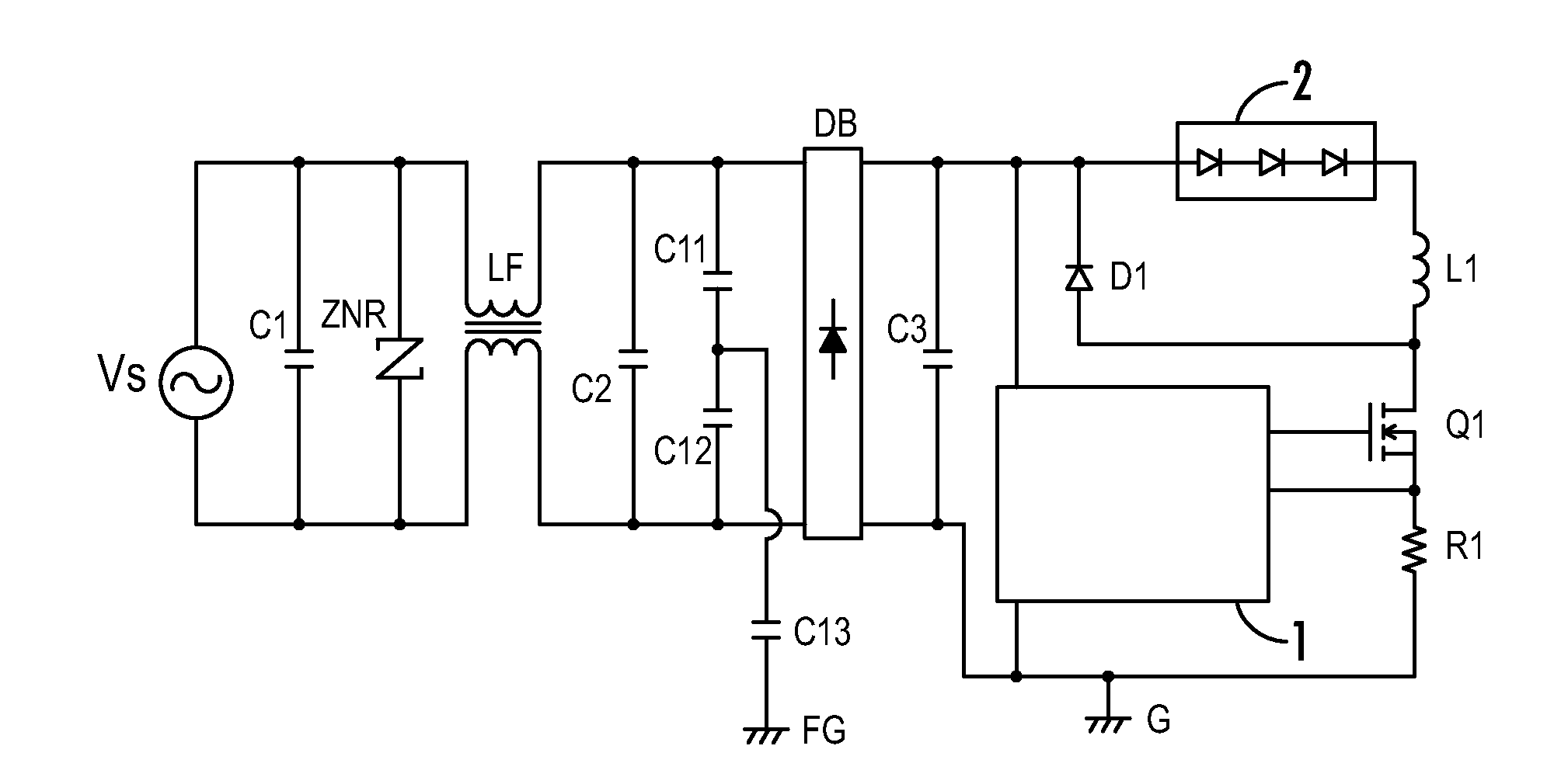
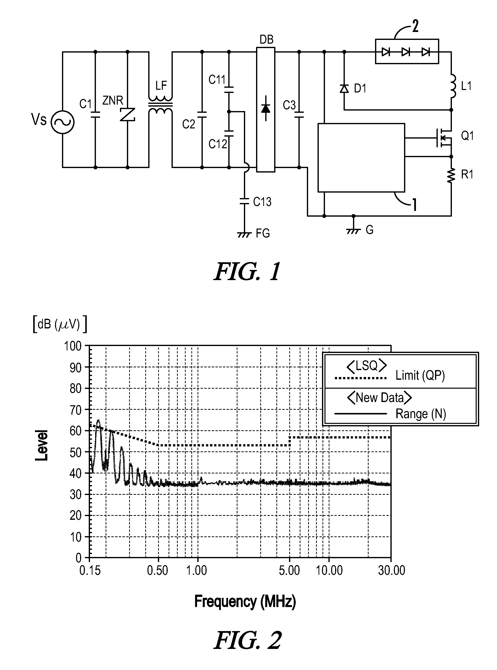
[0023]FIG. 1 is a circuit diagram according to the present invention. An alternating-current (AC) input terminal of a diode bridge DB is connected to a commercial AC power source Vs via a line filter LF. A parallel circuit of a first noise prevention capacitor C1 and a nonlinear resistor element ZNR is connected to a power-source side of the line filter LF. A second noise prevention capacitor C2 is connected to an output terminal of the line filter LF. A series circuit of capacitors C11 and C12 is connected to the noise prevention capacitor C2 in parallel. A connecting node of the capacitors C11 and C12 is connected to an earth ground or fixture ground FG via a capacitor C13.

[0024]A smoothing capacitor C3 is connected to a direct-current (DC) output terminal of the diode bridge DB. The smoothing capacitor C3 smoothes the pulsating voltage from the DC output terminal of the diode bridge DB. In one embodiment, the capacitance of the smoothing capacitor C3 is 1•F or less.

[0025]A negati...

second embodiment

[0041]Meanwhile, although not shown in the drawings, the DC-DC conversion circuit can be replaced by a step-down chopper circuit and is configured as a flyback converter circuit as in the

[0042]FIG. 7 is a cross-section view of an LED lamp fixture using the LED power-source circuit according to any one of the embodiments. The fixture chassis or housing 7 of the LED lamp fixture is attached to or recessed into a ceiling 9. The LED assembly 2 and the power-source circuit part 4 are incorporated into the fixture housing 7. The fixture hosing 7 can be formed of a metallic cylindrical body having an opening lower end, and the opening lower end can be covered with a light diffusion plate 8. The LED assembly 2 is arranged so as to face the light diffusion plate 8. Component 21 represents an LED mounting board, and the LED mounting board mounts LEDs 2a to 2d of the LED assembly 2.

[0043]The LED assembly 2 includes four LEDs 2a to 2d in this embodiment, and has a configuration where the LEDs 2...


PUM


Abstract

An LED power-source circuit includes an input filter circuit including noise prevention capacitors and a line filter, a diode bridge connected to the input filter circuit, a smoothing capacitor connected to an output of the diode bridge and having a capacitance of 1 μF or less, a DC-DC conversion circuit connected to the smoothing capacitor, and an LED assembly connected to an output of the DC-DC conversion circuit. Grounding capacitors are coupled to ground from an input power line between the line filter and the diode bridge. The total capacitance from the input power line to ground is set to be 1/200 or less of that of the smoothing capacitor.

Description

[0001]A portion of the disclosure of this patent document contains material that is subject to copyright protection. The copyright owner has no objection to the reproduction of the patent document or the patent disclosure, as it appears in the U.S. Patent and Trademark Office patent file or records, but otherwise reserves all copyright rights whatsoever.CROSS-REFERENCES TO RELATED APPLICATIONS[0002]This application claims benefit of the following patent application(s) which is / are hereby incorporated by reference: Japan Patent Application No. 2009-020698, filed Jan. 30, 2009.STATEMENT REGARDING FEDERALLY SPONSORED RESEARCH OR DEVELOPMENT[0003]Not ApplicableREFERENCE TO SEQUENCE LISTING OR COMPUTER PROGRAM LISTING APPENDIX[0004]Not ApplicableBACKGROUND OF THE INVENTION[0005]The present invention relates to LED power-source circuits and lamp fixtures using the same.[0006]Because the performance and longevity of light emitting diodes (LEDs) are steadily improving, general purpose light...

Claims


Application Information

Patent Timeline
Patent Type & Authority Applications(United States)
IPC IPC(8): H05B41/36
CPCH05B33/0809Y02B20/348Y02B20/346H05B33/0815Y02B20/30H05B45/375H05B45/3725H05B45/385
Inventor KUMADA, KAZUHIROKUROKI, YOSHIFUMIMIZUKAWA, HIROMITSU
Owner PANASONIC CORP
Why Eureka
Try Eureka