Pof strain sensor using phase measurement techniques

Inactive Publication Date: 2010-09-16
BROADCOM INT PTE LTD
View PDF11 Cites 10 Cited by
  • Summary
  • Abstract
  • Description
  • Claims
  • Application Information

AI Technical Summary

Benefits of technology

[0016]It is advantageous if the measurement fibers are connected to the mechanical component in such a way that during a deformation of the mechanical component the changes in length of the measurement fibers run in the opposite direction. This means, for example, that during a deformation of the mechanical component in a first direction the first measurement fiber is s

Problems solved by technology

Electrical sensors like these strain gauge sensors have the problem of being sensitive to electrical or electromagnetic disturbances.
Thus, such sensors can be disturbed or destroyed by the discharge of electrostatic charges on the rotor blades or by lightning strikes.
Drawbacks of using optical fiber-based sensors include their complex handling and their high mechanical sensitivity.
Furthermore, sensors based on the evaluation of change in polarisation have in many cases only low resolution or accuracy.
Another problem of sensors of this type, which can measure a plurality of measu

Method used


Image

  • Pof strain sensor using phase measurement techniques
  • Pof strain sensor using phase measurement techniques
  • Pof strain sensor using phase measurement techniques

Examples


Embodiment Construction

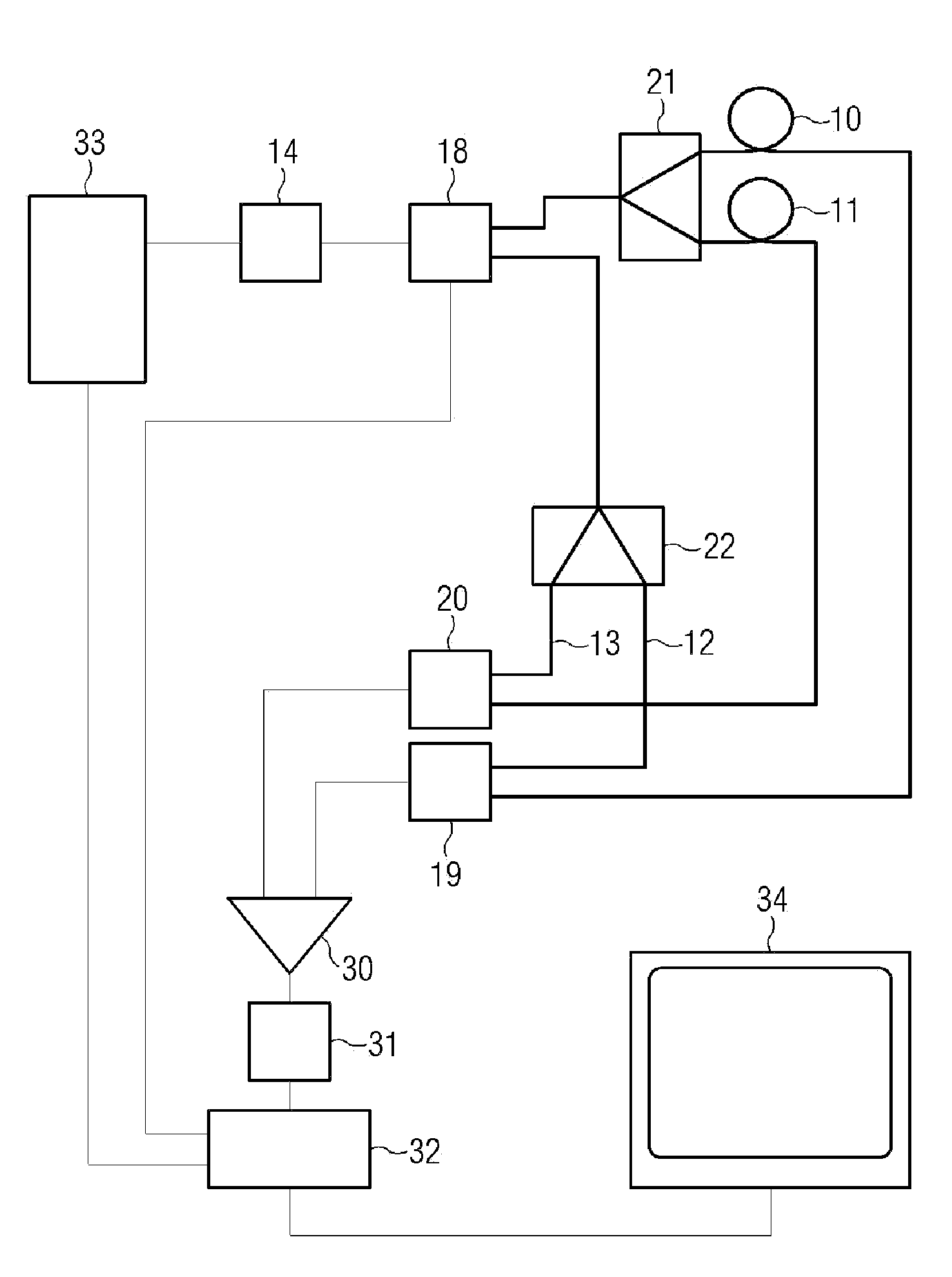
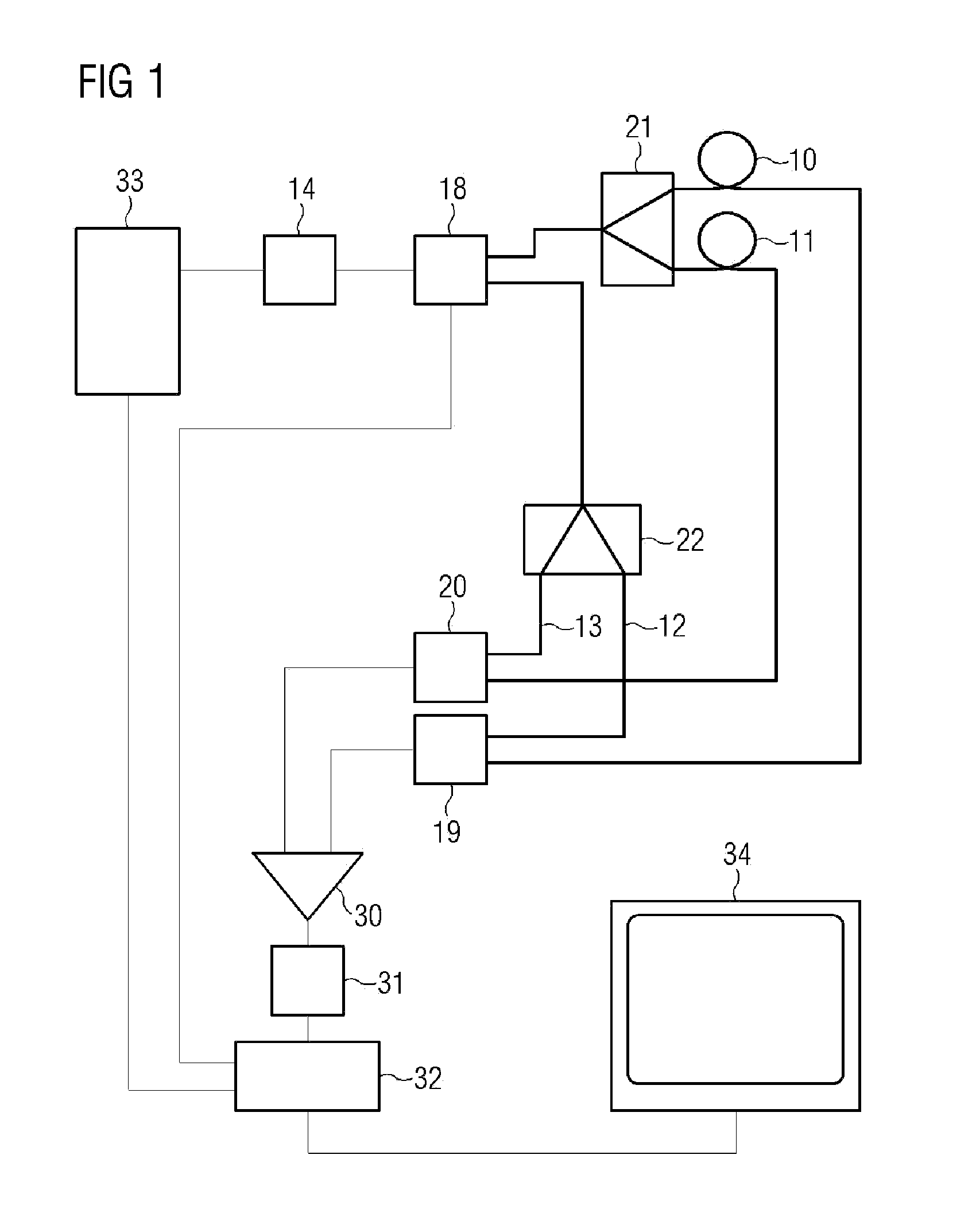
[0040]FIG. 1 shows an optical fiber sensor. A signal generator 33 generates a signal for modulating a first optical transmitter 14. The output signal of the first optical transmitter 14 is selectively supplied to a first Y-coupler 21 for the measurement path or a second Y-coupler 22 for the reference path via an optical changeover switch 18. The first Y-coupler 21 divides the signal into two parts for a first measurement fiber 10 and also a second measurement fiber 11. These two measurement fibers are preferably connected to a mechanical component in such a way that the two measurement fibers are deformed in opposite directions and are in this case approximately the same temperature. The output signal of the first measurement fiber 10 is supplied to a first optical receiver 19 and the output signal of the second measurement fiber 11 is supplied to a second optical receiver 20. The output signals of the two optical receivers are compared by means of a phase comparator 30. The phase d...


PUM


Abstract

An optical fiber sensor has a measurement path and a reference path. Both paths each consist of two optical fibers and are fed with modulated light. The fibers of the reference path have a predefined difference in length, whereas the fibers of the measurement path are the same length. All fibers are at approximately the same temperature. An evaluation circuit determines the phase differences in each case between the fibers of the measurement path and of the reference path. A measurement value calculated from the phase differences is then output.

Description

PRIORITY CLAIM[0001]This application is a continuation of pending International Application No. PCT / EP2008 / 062343 filed on Sep. 17, 2008, which designates the United States and claims priority from European Patent Application 07 116 533.6 filed on Sep. 17, 2007.BACKGROUND OF THE INVENTION[0002]1. Field of the Invention[0003]The invention relates to an optical sensor for measuring physical parameters on industrial components and structures, in particular on rotor blades of wind power plants.[0004]2. Description of the Relevant Art[0005]DE 10 2005 0016524 discloses a wind power plant in which operating states or anomalies on the rotor blades are determined by means of strain gauge sensors. Electrical sensors like these strain gauge sensors have the problem of being sensitive to electrical or electromagnetic disturbances. Thus, such sensors can be disturbed or destroyed by the discharge of electrostatic charges on the rotor blades or by lightning strikes.[0006]U.S. Pat. No. 4,773,753 d...

Claims


Application Information

Patent Timeline
IPC IPC(8): G02B6/00
CPCG01M11/086G01B11/18
Inventor SCHILLING, HARRYPOISEL, HANSZIEMANN, OLAFLUBER, MICHAELLOQUAI, SVEN
Owner BROADCOM INT PTE LTD
Why Eureka
Try Eureka