High-temperature capacitors and methods of making the same

a capacitor and high-temperature technology, applied in the field of high-temperature polymer film capacitors, can solve the problems of low resonant frequency, high dissipation factor of capacitors used to control ripple current, and insufficient current mlp technology in many high-performance, high-temperature applications

a capacitor and high-temperature technology, applied in the field of high-temperature polymer film capacitors, can solve the problems of low resonant frequency, high dissipation factor of capacitors used to control ripple current, and insufficient current mlp technology in many high-performance, high-temperature applications

US20100244585A1Inactive Publication Date: 2010-09-30GENERAL ELECTRIC CO

Image

  • High-temperature capacitors and methods of making the same
  • High-temperature capacitors and methods of making the same
  • High-temperature capacitors and methods of making the same

Examples


Embodiment Construction

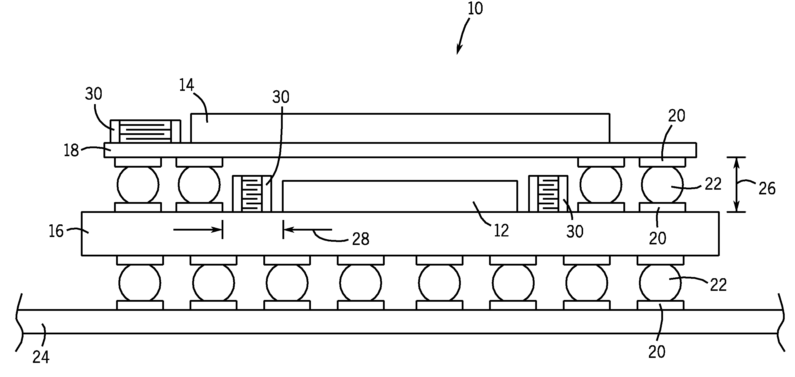
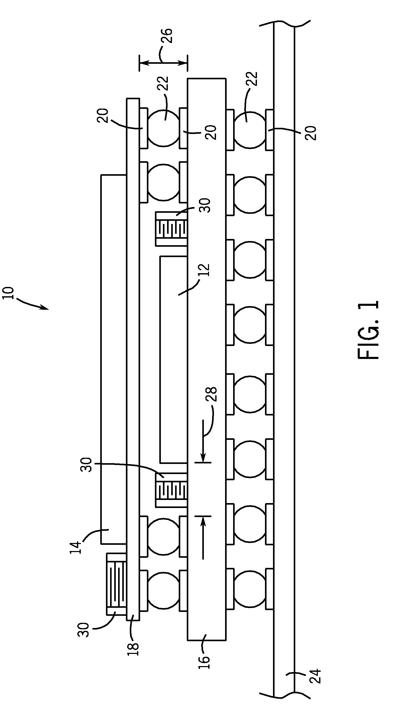
[0017]As discussed in detail below, embodiments of the present invention include a stacked MLP capacitor that is operable at high temperatures and exhibits improved electrical properties. Methods of manufacturing stacked MLP capacitors are also described. Some of the dielectric properties considered herein include dielectric constant, equivalent series resistance (ESR), equivalent series inductance (ESL). As used herein, dielectric constant is a ratio of the amount of electrical energy stored in the dielectric and the amount of electrical energy stored in a vacuum under an equivalent applied voltage. Equivalent series resistance (ESR) is the real, i.e. resistive, component of the complex impedance of a capacitor due to the resistivity of the metallic leads and electrodes and other non-ideal characteristics of the capacitor. Equivalent series inductance (ESL) is the inductive component of the complex impedance of a capacitor due to the inductive properties of the capacitor connection...


PUM

PropertyMeasurementUnit
heightaaaaaaaaaa
frequenciesaaaaaaaaaa
voltagesaaaaaaaaaa

Abstract

High-temperature, multiple-layer polymer (MLP) capacitors with a stacked electrode arrangement are disclosed. The capacitor electrodes are separated by a polymer dielectric that is stable at high temperatures. In some embodiments, the polymer dielectric also has a high permittivity and is filled with high-permittivity nanoparticles, which enables the capacitor to achieve a very high capacitance density.

Description

BACKGROUND OF THE INVENTION[0001]The subject matter disclosed herein relates generally to electrical capacitors, and more particularly to the configuration of high-temperature polymer-film capacitors and the dielectric materials used in therein.[0002]Discrete capacitors are used in many electronic applications, such as noise suppression, filtering, electrical decoupling, bypassing, termination, and frequency determination. Over the last decade, significant advances in capacitor reliability and performance have been achieved through a combination of advanced manufacturing techniques and new materials, particularly in the field of multiple-layer polymer capacitors (MLPs). Despite recent advances, however, current MLP technology may be insufficient in many high-performance, high-temperature applications. For example, efficient electronic packaging techniques such as package-on-package (POP) provide limited spacing for embedded capacitors. Furthermore, typical MLPs are too bulky to prov...

Claims


Application Information

Patent Timeline
30 Sep 2010
Publication
US20100244585A1
IPC
H01G4/30; H02M3/06; H05K7/00
CPC
H01G4/183; Y10T29/435; H01G4/32; H01G4/30
Inventors
TAN, DANIEL QI; CAO, YANG