Ultra wide-band dual-frequency combiner

a dual-frequency combiner and wide-band technology, applied in the field of processing devices, can solve the problems of large volume of arcs, small power capacity, difficult control in mass production, etc., and achieve the effects of small signal loss, large power capacity, and reduced product siz

Active Publication Date: 2010-09-30
COMBA TELECOM TECH (GUANGZHOU) CO LTD
View PDF4 Cites 12 Cited by
  • Summary
  • Abstract
  • Description
  • Claims
  • Application Information

AI Technical Summary

Benefits of technology

[0014]Compared with the conventional technique, the present invention at least has the following advantages: 2 G / 3 G ultra wideband dual-frequency combiner realized by the coaxial resonator band pass filters in accordance with the present invention realizes the mutual isolation of direct current channel and radio frequency signal channel by a special way. Parameter distributed capacitors can reduce the size of the product using the ultra wideband dual-frequency combiner in accordance with the present invention. Moreover, ultra wideband dual-frequency combiner according to the present invention has a redesigned configuration, so as to achieve the advantages of small signal loss, large power capacity and high isolation between the channels.

Problems solved by technology

The disadvantages of these products arc large volume and small power capacity.
Additionally, the passive intermodulation index is determined by characters or the dielectric substrate material and therefore, it is difficult to control in mass production.

Method used


Image

  • Ultra wide-band dual-frequency combiner
  • Ultra wide-band dual-frequency combiner
  • Ultra wide-band dual-frequency combiner

Examples


Embodiment Construction

[0021]Reference will now be made to the drawings to describe an embodiment of the present invention in detail.

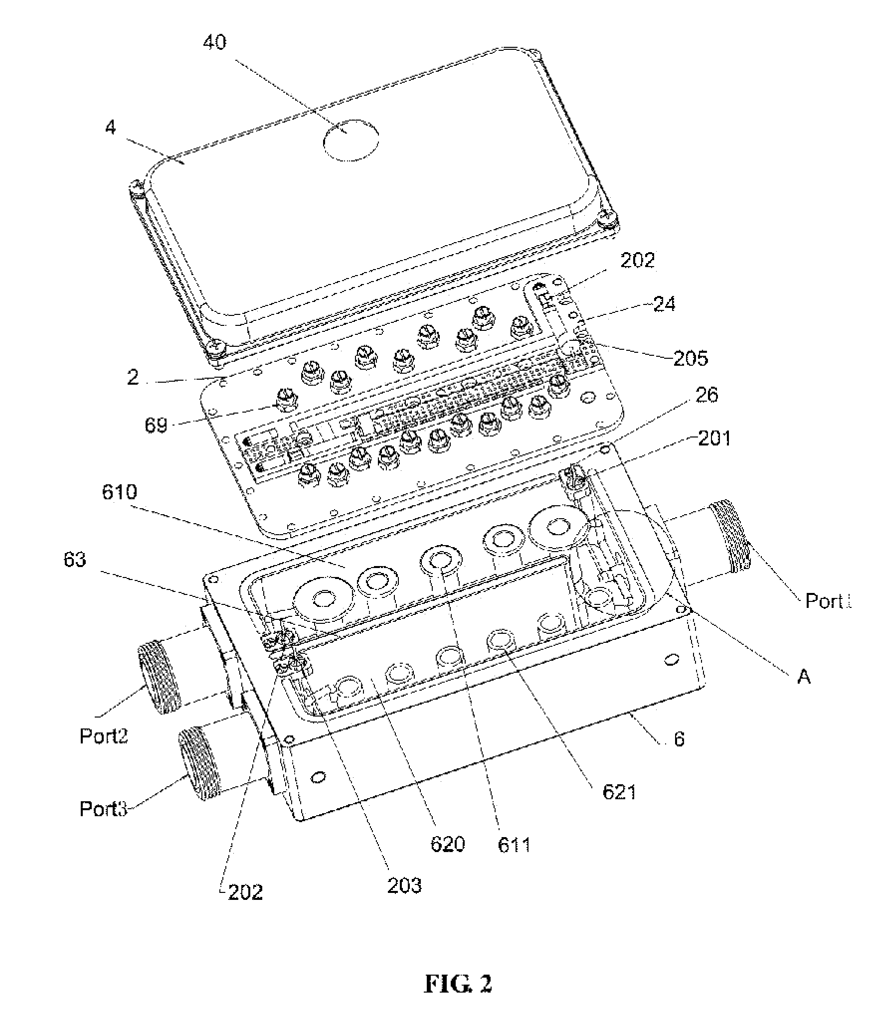
[0022]Referring to FIG. 2, an ultra wide band double frequency combiner of the invention is mainly used for combining 2 G signals and 3 G signals.

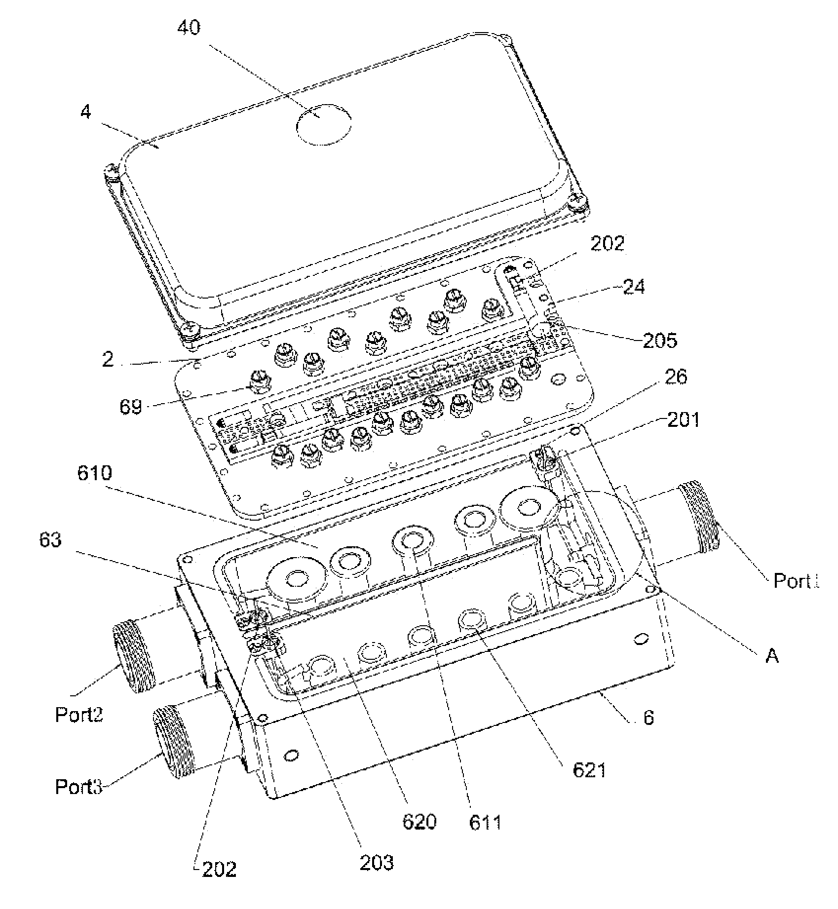
[0023]As shown in FIG. 2, the combiner is generally a box including a housing 6, a board 2 and a cover 4.

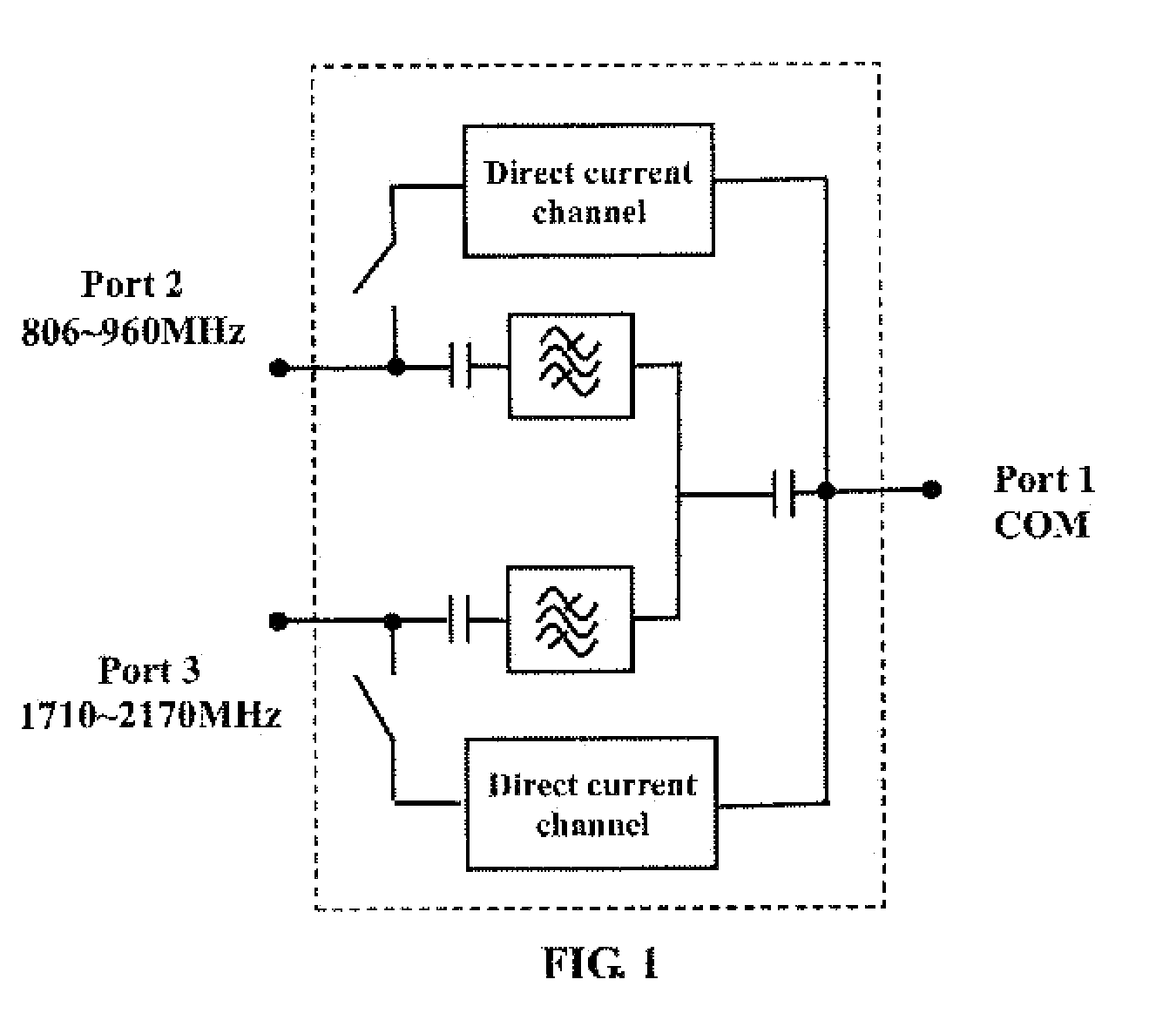
[0024]A first port (Port 2) and a second port (Port 3) are defined at the left side of the housing 6 to receive radio frequency signal with 806-960 MHz and 1710-2170 MHz, respectively. A combination port (Port 1) is defined at the right side of the housing 6 for outputting a radio frequency signal which is combined radio frequency signal from the first port (Port 2) and the radio frequency signal from the second port (Port 3), or for inputting shunt signal to the first port (Port 2) and the second port (Port 3).

[0025]Two radio frequency channels, namely the first radio frequency channel and the second radio frequency channel, ar...


PUM


Abstract

An ultra wideband dual-frequency combiner includes a combination port (Port 1), a first port (Port 2) a second port (Port 3), two coaxial resonator band pass filters and two direct current channels. The first direct current channel is connected between the first port (Port 2) and the combination port (Port 1). The second direct current channel is connected between the second port (Port 3) and the combination port (Port 1). One end of the first coaxial resonator hand pass filters (610, 611) is electrically connected with the first port (Port 2) via a first blocking capacitor. One end of the second coaxial resonator hand pass filter (620, 621) is electrically connected with the second port (Port 3) via a second blocking capacitor. The other ends of the first coaxial resonator band pass filter and the second coaxial resonator band pass filter are connected with the combination port (Port 1) via a third blocking capacitor. The blocking capacitors are parameter distributed capacitors.

Description

FIELD OF THE INVENTION[0001]The present invention generally relates to processing devices for combining the second generation communication system with the third generation communication system and, more specifically, to an ultra wideband dual-frequency combiner.BACKGROUND OF THE INVENTION[0002]With the rapid development of mobile communication, application ways of multi-system with co-base station and shared antenna feeder are widely used at present, to share resources and reduce cost of the system device. Dual-frequency combiner is a necessary microwave device in shared antenna feeder system of 2G / 3 G. The combiner is used for combining and distributing the different systems, to save feed cables, simplify system and reduce cost. Additionally, the power supply of the device in the base station tower is realized by the radio frequency cable. The combiner connected in series with the feed cable should have the performance of transmitting direct current power.[0003]Referring to the sc...

Claims


Application Information

Patent Timeline
Patent Type & Authority Applications(United States)
IPC IPC(8): H03H7/46
CPCH01P1/2136H01P1/2133
Inventor DI, YINGJIEHE, TAOHE, BINSHU, MENGMENGHUANG, JINGMIN
Owner COMBA TELECOM TECH (GUANGZHOU) CO LTD
Why Eureka
Try Eureka