
Light source unit utilizing laser for light source and projector

a technology of light source and laser, which is applied in the direction of lighting support devices, lighting and heating apparatus, instruments, etc., can solve the problems of affecting the eyes of human beings, reducing the utilization efficiency of light emitted from individual light emitting diodes, and reducing the utilization efficiency of light emitting diodes

Active Publication Date: 2010-09-30
CASIO COMPUTER CO LTD
View PDF12 Cites 113 Cited by
  • Summary
  • Abstract
  • Description
  • Claims
  • Application Information

AI Technical Summary

Benefits of technology

[0013]The invention has been made in view of the problems inherent in the related art and an object thereof is to provide a light source unit which utilizes a laser diode and which is much safer than the related art light source units and a small, thin projector which includes the same light source unit.

Problems solved by technology

In a case where a plurality of light emitting diodes are used to form a light source unit, however, due to an increase in the number of bright points of the light source unit, it becomes difficult to concentrate light emitted from the individual bright points to a single point by an optical system once it has been so emitted, leading to a problem that the utilization efficiency of light emitted from the individual light emitting diodes is reduced.
In addition, since the value of Etendue is large, there is much light which is unnecessary or is not used, leading to a problem that the utilization efficiency of the light emitting diodes is reduced.
Although a higher output of the laser diode than that of the light emitting diode can compensate for the insufficient output of the light emitting diode, since coherent light (light with complete phase relationships) is emitted, when laser light is emitted directly to the outside of the light source unit or a projector which includes the light source unit in the form of coherent light, there exists a danger in which the eyes of a human being are badly affected.
In the related art in which the laser diode is used as the light source, although there is no risk of light emitted from the laser diode is emitted directly to the outside of the projector in such a state that the fluorescent materials are excited, in the event that the fluorescent materials are dislodged due to heat or deterioration with age, there has been a fear that light emitted from the laser diode is emitted directly to the outside of the projector.
As described, since light emitted from the laser diode constitutes coherent light and its output is very high, should such laser light be emitted directly to the outside of the projector even for a minute period of time, a seriously dangerous thing will result therefrom.
In addition, in addition to the emission of laser light to the outside of the projector, in the event that high-output coherent light which is light emitted from the laser diode is shone on to various types of devices disposed within a housing of electric equipment, heat stays where the coherent light is so shone, which triggers a risk that the devices fail or a risk that adhesives are deteriorated with age.

Method used


Image

  • Light source unit utilizing laser for light source and projector
  • Light source unit utilizing laser for light source and projector
  • Light source unit utilizing laser for light source and projector

Examples


Embodiment Construction

[0023]Hereinafter, a best mode for carrying out the invention will be described by use of the accompanying drawings. However, in the following embodiment, although various preferred technical limitations will be described as being made for carrying out the invention, the scope of the invention is not limited at all to the following embodiment and illustrated examples.

[0024]A summary of a mode for carrying out the invention will be described below.

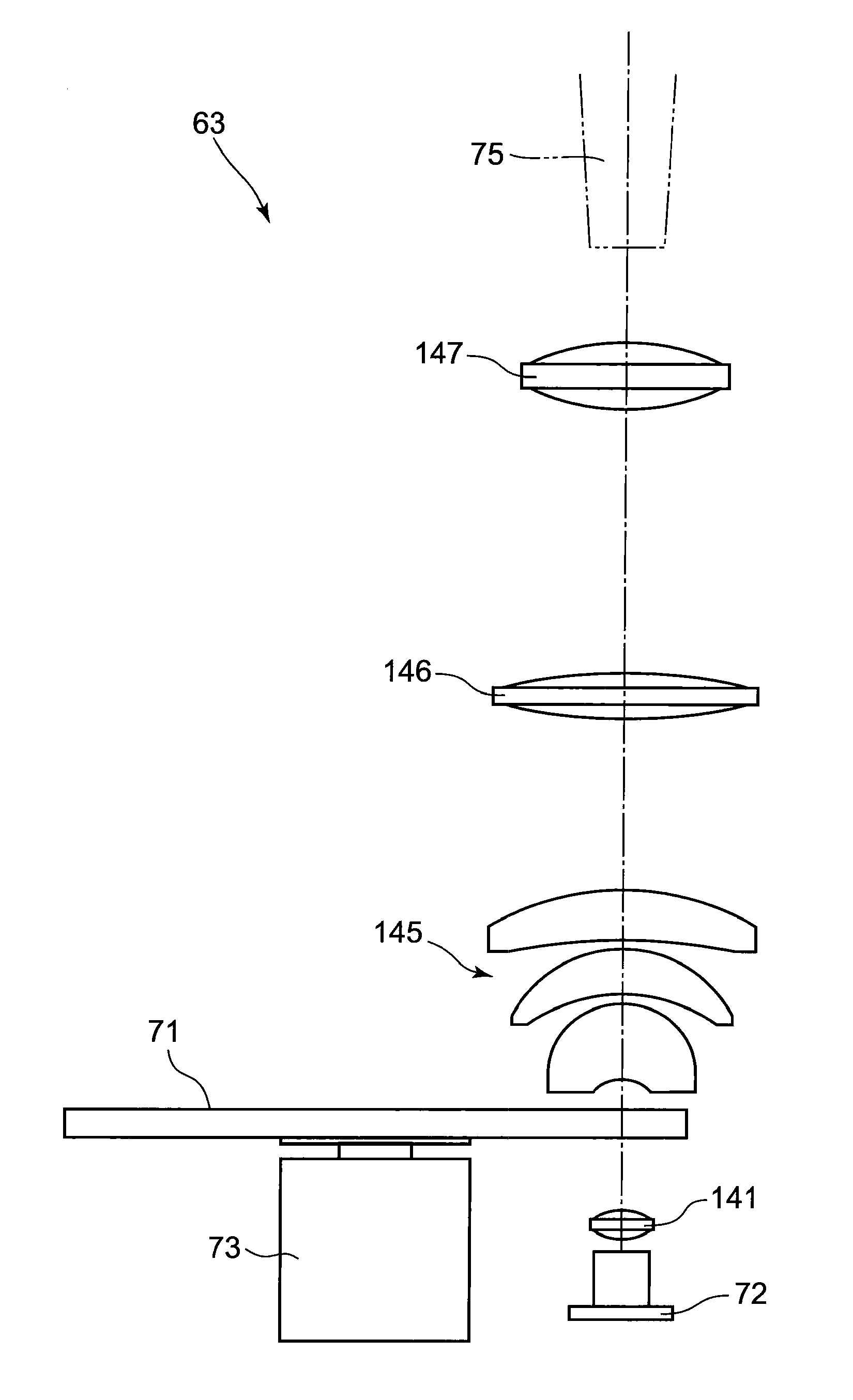
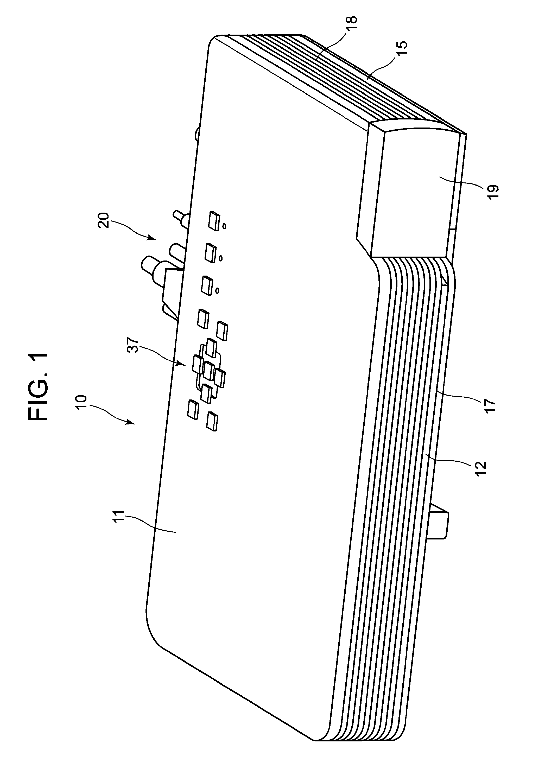
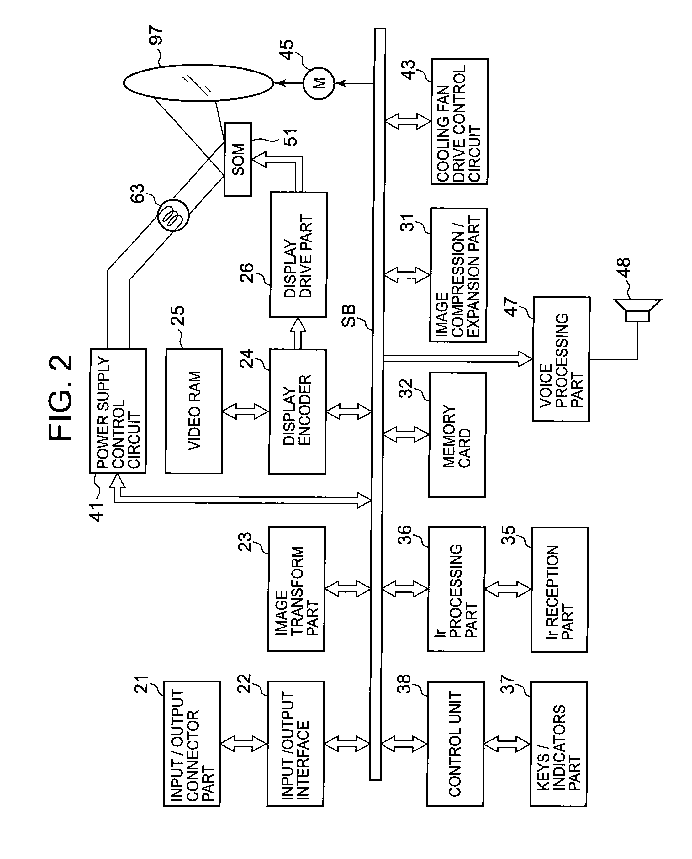
[0025]A projector 10 includes a light source unit 63, a light guiding device 75, a display device 51, a projection side optical system 90, and a projector control means. This light source unit 63 includes a light source 72 for emitting laser light in the wavelength band of blue, a light emitting wheel 71 disposed on an optical axis of the light source 72, and a wheel motor 73 for driving to rotate the light emitting wheel and emits light in predetermined wavelength bands by controlling the light emitting wheel 71.

[0026]In addition, the ligh...


PUM

PropertyMeasurementUnit
wavelengthaaaaaaaaaa
peak wavelengthaaaaaaaaaa

Abstract

A projector includes a light source unit 63, a light guiding device 75, a display device, a projection side optical system and a projector control means, the light source unit 63 includes a light source 72 which emits laser light in the wavelength band of blue, a light emitting wheel 71 disposed on an optical axis of the light source 72 and a wheel motor 73 for driving to rotate the light emitting wheel 71, and the light emitting wheel 71 is formed of a circular substrate having a diffusion layer on a predetermined surface thereof, the diffusion layer being made up of minute irregularities which are formed directly on a surface of the circular substrate.

Description

CROSS-REFERENCE TO RELATED APPLICATIONS[0001]This application is based upon and claims the benefit of priority under 35 USC 119 of Japanese Patent Application No. 2009-085422 filed on Mar. 31, 2009, the entire disclosure of which, including the description, claims, drawings and abstract, is incorporated herein by reference.BACKGROUND OF THE INVENTION[0002]1. Field of the Invention[0003]The present invention relates to a light source unit including a light emitting wheel and a projector including the light source unit.[0004]2. Description of the Related Art[0005]In these days, data projectors are used in many cases as image projection apparatuses which project screens or video images of personal computers and further images based on image data stored in memory cards on to a screen. These projectors are such that light emitted from a light source is concentrated on a micromirror device called a DMD (Digital Micromirror Device) or a liquid crystal plate for display of a color image on ...

Claims


Application Information

Patent Timeline
Patent Type & Authority Applications(United States)
IPC IPC(8): G03B21/20F21V3/04G02B27/48F21V9/16F21S4/00
CPCG02B5/0215G03B21/204F21V9/16F21V7/30F21V9/32F21V9/38F21V9/45F21V13/14G03B21/2033H04N9/3161
Inventor OGURA, NAOTSUGU
Owner CASIO COMPUTER CO LTD
Learn More