Perpendicular magnetic recording medium

a magnetic recording medium and perpendicular technology, applied in the field of perpendicular magnetic recording medium, can solve the problems of reducing snr, reducing snr, and prone to head crash or thermal asperity failure, so as to increase the recording density, and reduce the surface roughness

Active Publication Date: 2010-09-30
WESTERN DIGITAL TECH INC
View PDF4 Cites 77 Cited by
  • Summary
  • Abstract
  • Description
  • Claims
  • Application Information

AI Technical Summary

Benefits of technology

[0031]Grains of an amorphous material have no crystal structure. Therefore, a layer made of the amorphous material is irregularly formed on the soft magnetic layer. Therefore, according to the above-mentioned configuration, it is possible, by the layer made of amorphous NiTa or amorphous CrTa, to smooth the surface of the soft magnetic layer to thereby reduce the surface roughness of the soft magnetic layer and thus the interface roughness (boundary roughness) of

Problems solved by technology

However, as described above, as the flying height of the magnetic head is reduced, the head crash or the thermal asperity failure tends to occur more easily.
However, if the thickness of the underlayer is simply reduced, the crystal orientation of the magnetic recording layer cannot be sufficiently aligned to cause a reduction in SNR.
Therefore, the underlayer cannot be thoughtlessly reduced in t

Method used


Image

  • Perpendicular magnetic recording medium
  • Perpendicular magnetic recording medium
  • Perpendicular magnetic recording medium

Examples


embodiment

Perpendicular Magnetic Recording Medium

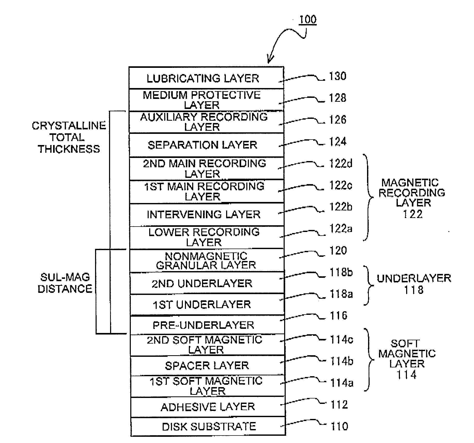
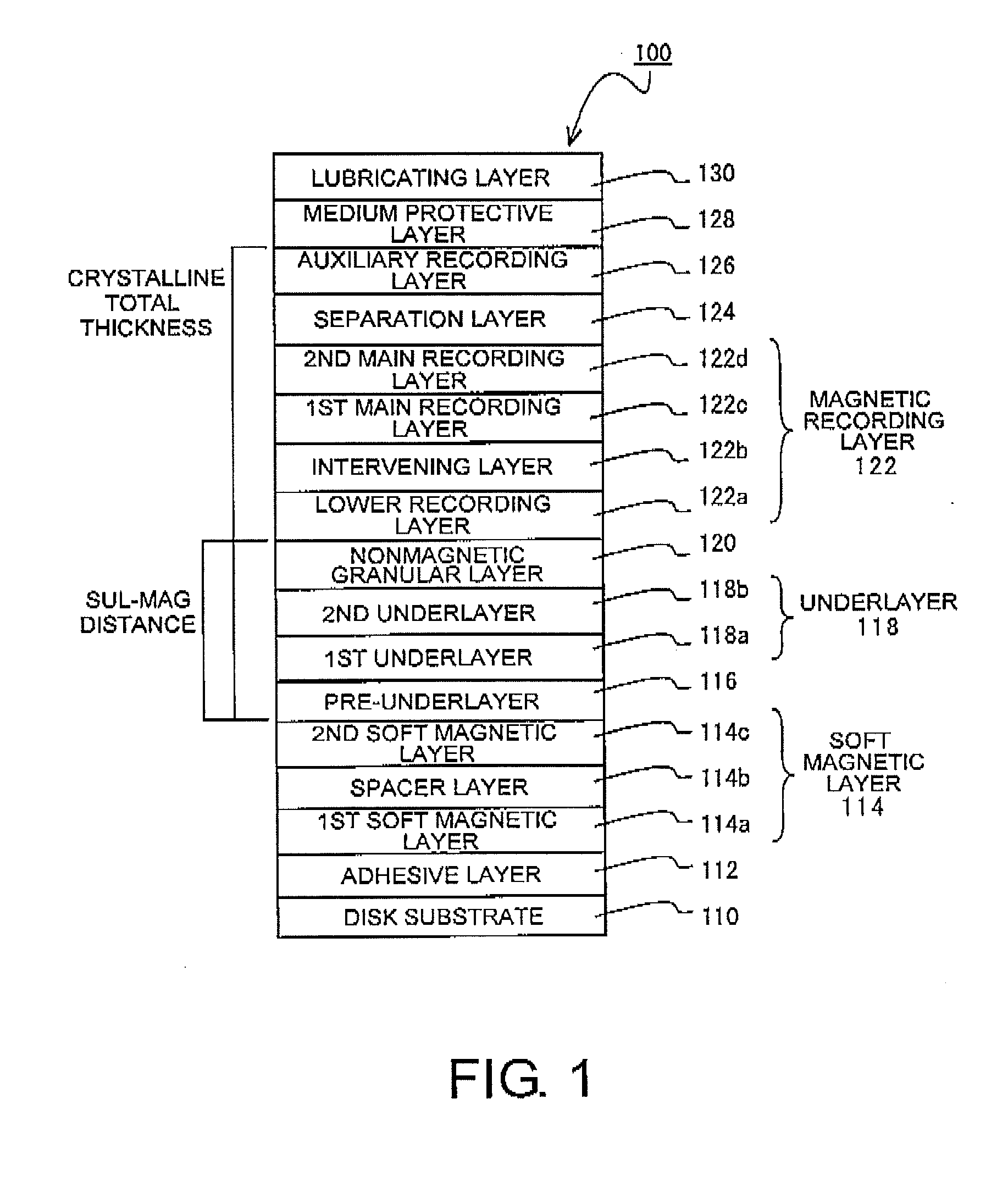
[0038]FIG. 1 is a diagram for explaining the structure of a perpendicular magnetic recording medium 100 according to this embodiment. The perpendicular magnetic recording medium 100 shown in FIG. 1 comprises a disk substrate 110, an adhesive layer 112, a first soft magnetic layer 114a, a spacer layer 114b, a second soft magnetic layer 114c, a pre-underlayer 116, a first underlayer 118a, a second underlayer 118b, a nonmagnetic granular layer 120, a lower recording layer 122a, an intervening layer 122b, a first main recording layer 122c, a second main recording layer 122d, a separation layer 124, an auxiliary recording layer 126, a medium protective layer 128, and a lubricating layer 130. The first soft magnetic layer 114a, the spacer layer 114b, and the second soft magnetic layer 114c cooperatively form a soft magnetic layer 114. The first underlayer 118a and the second underlayer 118b cooperatively form an underlayer 118. The lower recording la...

example

[0082]Using an evacuated film forming apparatus, the layers from the adhesive layer 112 to the auxiliary recording layer 126 were formed in sequence on the disk substrate 110 in an Ar atmosphere by a DC magnetron sputtering method. The composition of the adhesive layer 112 was CrTi. In the soft magnetic layer 114, the composition of the first soft magnetic layer 114a and the second soft magnetic layer 114c was CoFeTaZr and the composition of the spacer layer 114b was Ru. The composition of the pre-underlayer 116 was NiW. As the first underlayer 118a, a Ru film was formed in an Ar atmosphere at a predetermined pressure (low pressure: e.g. 0.6 Pa to 0.7 Pa). As the second underlayer 118b, a Ru (RuO) film containing oxygen was formed, using a target containing oxygen, in an Ar atmosphere at a pressure (high pressure: e.g. 4.5 Pa to 7 Pa) higher than the predetermined pressure. The composition of the nonmagnetic granular layer 120 was nonmagnetic CoCr—SiO2. In the lower recording layer ...


PUM


Abstract

In a perpendicular magnetic recording medium having, over a substrate, a magnetic recording layer, an underlayer made of Ru or a Ru compound and provided below the magnetic recording layer, a pre-underlayer made of a nonmagnetic crystalline material, and a soft magnetic layer provided below the pre-underlayer, when the difference between the highest point and the lowest point of unevenness of the interface between the soft magnetic layer and the pre-underlayer, derived by a cross-sectional TEM image, is given as an interface roughness (nm) and the distance between the soft magnetic layer and the magnetic recording layer, excluding the soft magnetic layer and the magnetic recording layer, is given as a SUL-MAG distance (nm), interface roughness (nm)≦0.4 (nm) and interface roughness×SUL-MAG distance (nm)≦12 (nm) are satisfied.

Description

[0001]This application is based upon and claims the benefit of priority from Japanese Patent Application No. 2009-087759, filed on Mar. 31, 2009, and Japanese Patent Application No. 2010-077948, filed on Mar. 30, 2010, the disclosures of which are incorporated herein in their entirety by reference.TECHNICAL FIELD[0002]This invention relates to a perpendicular magnetic recording medium adapted to be mounted in a perpendicular magnetic recording HDD (hard disk drive) or the like.BACKGROUND ART[0003]Various information recording techniques have been developed following the increase in volume of information processing in recent years. Particularly, the areal recording density of a HDD using the magnetic recording technique has been increasing at an annual rate of about 100%. Recently, the information recording capacity exceeding 200 GB has been required per 2.5-inch magnetic recording medium adapted for use in a HDD or the like. In order to satisfy such a requirement, it is necessary to...

Claims


Application Information

Patent Timeline
IPC IPC(8): G11B5/33
CPCG11B5/66G11B5/82G11B5/7325G11B5/667G11B5/737G11B5/676G11B5/674
Inventor ONOUE, TAKAHIRO
Owner WESTERN DIGITAL TECH INC
Why Eureka
Try Eureka