[0012]The present invention seeks to provide a new method and device for self-propulsion along internal passageways, having a simple
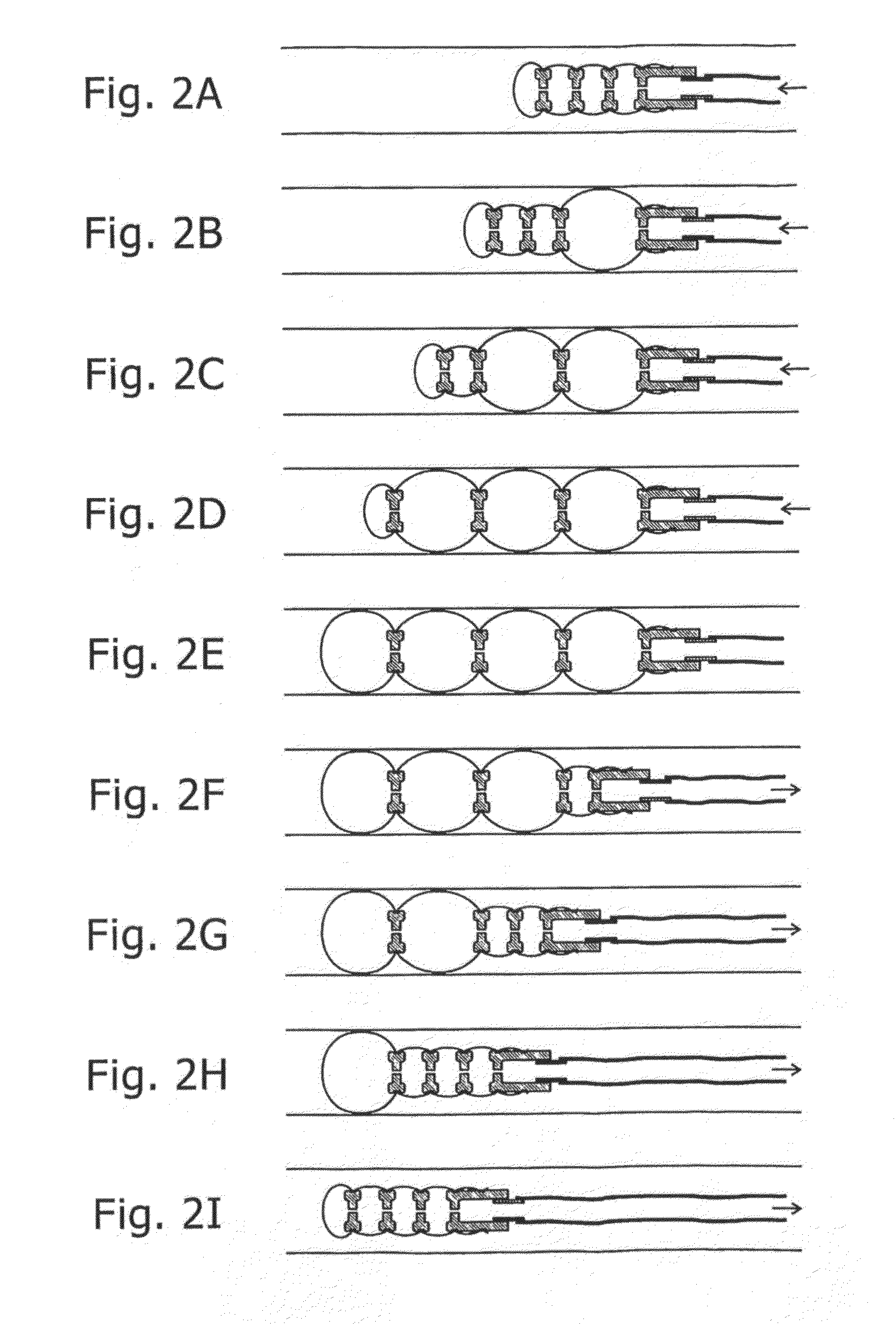
control system requiring only a single inflation and deflation cycle to propel the device. The device utilizes the dynamic behavior of fluid connected inflated balloons, whereby a time
delay in the passage of inflating fluid from rearmost to foremost
balloon is utilized to inflate the balloons in sequence beginning with the rearmost, and ending with the foremost. Conversely, this same time
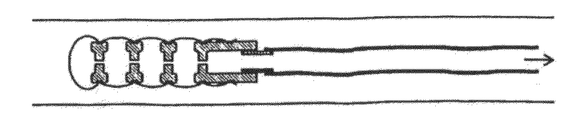
delay ensures that deflation of the balloons also proceeds in sequence beginning with the rearmost, and ending with the foremost. The device of the present invention uses a series of
inflatable chambers to make up the
traction unit, with the device sequentially gripping preferably the inside wall of the passageway with the chamber or chambers disposed at the rear or proximal end of the series while the device expands forward with inflation of the other chambers, and then gripping preferably the inside wall of the passageway with the chamber or chambers situated at the front or distal end of the series, while the device pulls up its rear end with deflation of the other chambers. By this means, no reliance is necessary on the physical situation present in the rearward tract of the passageway to provide backward
frictional resistance to the trailing inflation tube, and the trailing tube can be made of a highly flexible and resilient material, such that it causes no friction or damage to the passageway being traversed. At the same time, the
radial pressure which needs to be applied to the inside walls of the passageway being negotiated is minimal, since there is minimal trailing friction to overcome. Furthermore, according to further preferred embodiments of the present invention, in which the fluid source is not supplied by means of a supply tube, but is provided
on board, the device is able to operate independently of its mechanical surroundings.
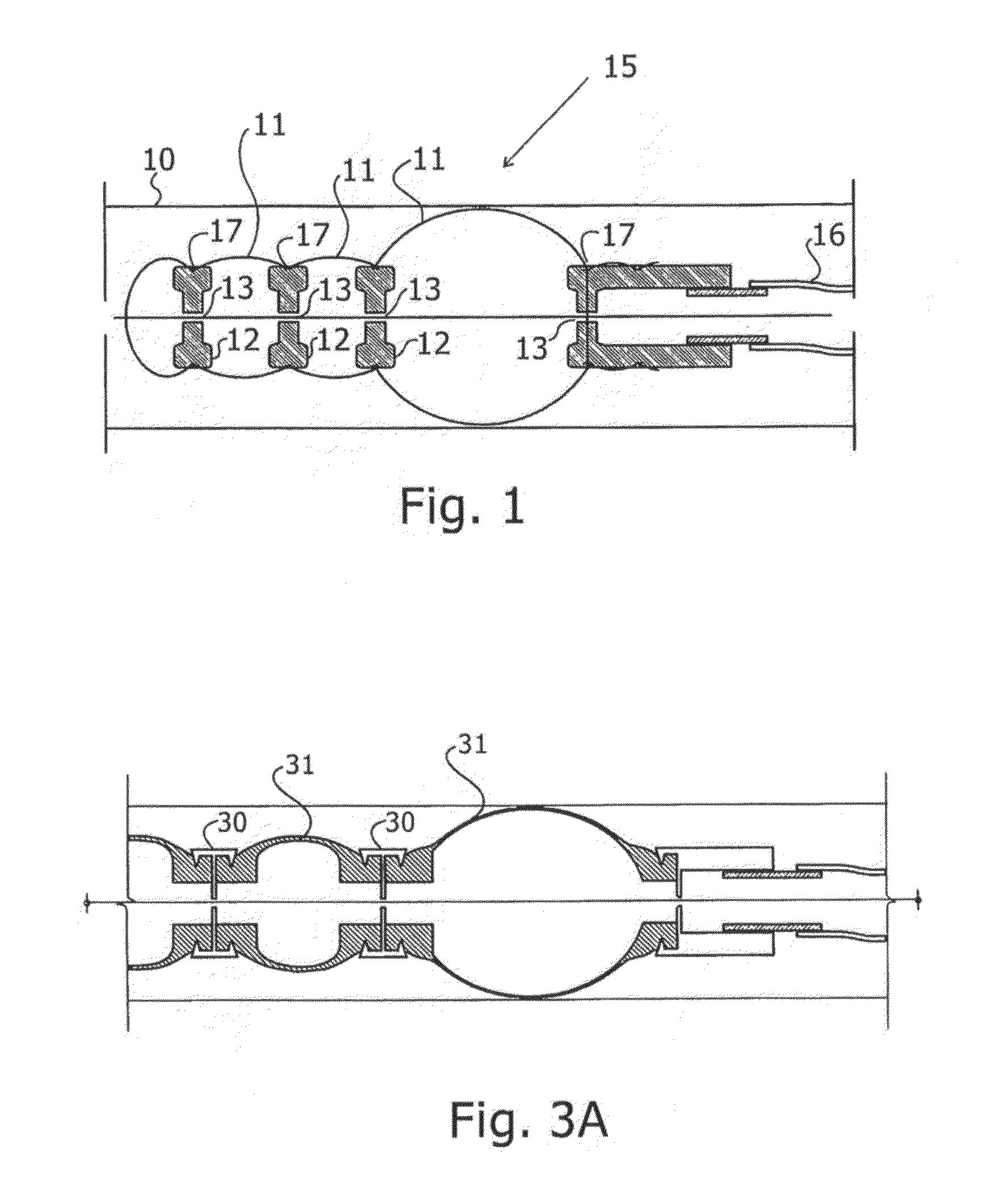
[0013]The device is operable with a series of only two inflatable chambers, each of which expands radially and axially when inflated, but the use of more than two chambers may have an
advantage in that the
radial pressure on the walls is spread out over more chambers, thus reducing the
internal pressure required to anchor the relevant chambers of the device. Furthermore, the use of a larger number of chambers may enable larger payloads to be transported or pulled by the device.
[0014]The device of the present invention has a number of other advantages, either alone or in combination, over prior art devices:(i) The device itself may be completely passive, and does not need to incorporate any actuators, engines, valves or electrical controllers
on board. If required, such components may be located remotely from the device outside of the body. For those preferred embodiments where the device is autonomous, or untethered, such components may then be mounted on-board.(ii) It may be fabricated from flexible materials only, to enable easy access to most interior cavities, and, when used in medical applications, to ensure minimum injuries and trauma to the inner tissues of the passageways of the subject.(iii) It has only a single supply line, to enable a small, flexible and low-drag “
tail”. Additional tubes may be added to provide special functions, unrelated to the motive aspects of the device, such as the injection of medication at the
device tip, or an X-
ray opaque medium.(iv) Lack of inflation of one or more sections, for instance due to a narrow section of the passageway, does not stop the device from functioning. The following balloons will receive the required
fluid supply in that case.(v) The propulsion
system applies itself to the interior wall of the passageway or cavity over a large area and preferably covering several cells, thereby reducing the forces applied on the tissue, and reducing potential injury thereto.(vi) The
system can be constructed is such a way that keeps the inner lumen free for
insertion of an
endoscope,
guide wires, and other surgical tools.(vii) The balloons can be distributed along a long length of the passageway, so the propulsion effect is distributed along a long region of the passageway. This, for example, allows use in the intestine or any other long curved passageway.(viii) The annular structure of the
balloon enables the device to be designed such that its gripping pressure is applied to an inner guide wire, and the unit advances by “creeping” along this guide wire. In this way, motion can be achieved without the application of pressure to the outer wall of the passageway. This may be important, for example, to avoid applying pressure to unstable coronary plaques, or to prevent harm the inner walls.

