GNSS method and receiver with camera aid

a receiver and camera technology, applied in the direction of navigation instruments, traffic control systems, instruments, etc., can solve the problems of 130 dbmw for gps signals on earth surface, requiring a high processing power, and nominally becoming too weak, so as to achieve easy integration and use

Active Publication Date: 2010-09-30
QUALCOMM INC
View PDF6 Cites 47 Cited by
  • Summary
  • Abstract
  • Description
  • Claims
  • Application Information

AI Technical Summary

Benefits of technology

[0016]It is an aim of the present invention to provide a better resiliency for a navigation method and system making the best use of the available resources.
[0024]The device and method according to the invention provide a seamless navigation system provided with a backup position information supplier when GPS signals are weak or not available, with limited requirements in terms of processing power. They can be easily integrated and used in existing portable devices provided with cameras, like new generation mobile phones.

Problems solved by technology

Usually, INS systems are able to provide more reliable positioning information but are also quite expensive and require a high processing power.
The internal clock of the GPS is usually affected by a large error with respect to the GPS satellite clocks.
One issue that arises with GPS and other GNSS systems is that the signal strength, which is typically of −130 dBmW for the GPS signals on earth surface is, nominally, becomes too weak when further attenuated whenever the view of the sky is obstructed, and especially within buildings.
In the zones where the GPS signal reception quality is bad and accordingly the signal-to-noise ratio (SNR) too high, a.k.a. urban canyons, the GPS signals can be lost.
This solution provides indeed a better accuracy and resiliency for the navigation, but on the other hand it inherently implies substantial hardware overhead for the synchronization and requires significant processing power.
This solution is thus not suited for small portable devices with limited processing power and space.
This solution does not use yet any visual means as a back-up data supplier for GPS aiding.

Method used


Image

  • GNSS method and receiver with camera aid
  • GNSS method and receiver with camera aid
  • GNSS method and receiver with camera aid

Examples


Embodiment Construction

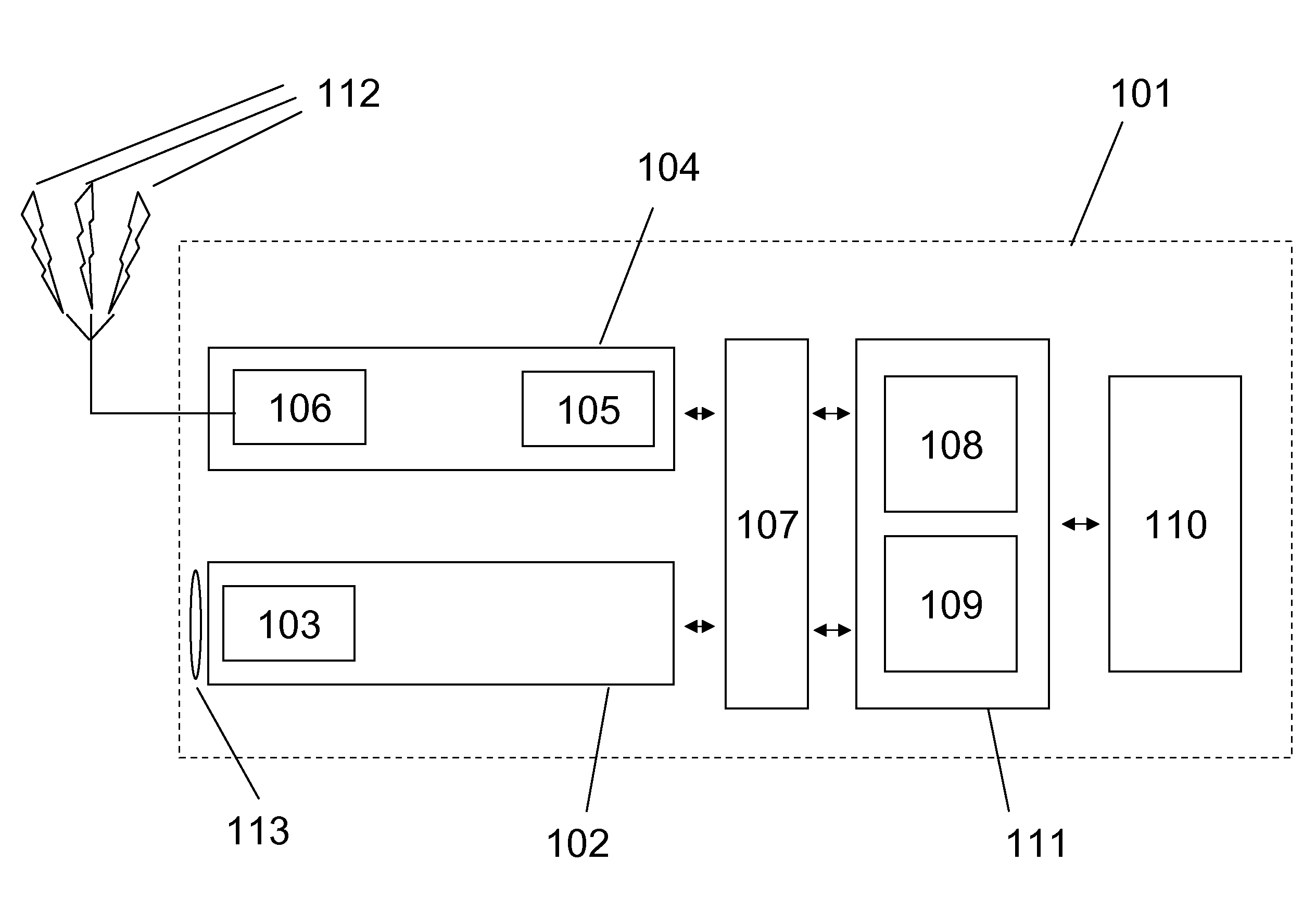
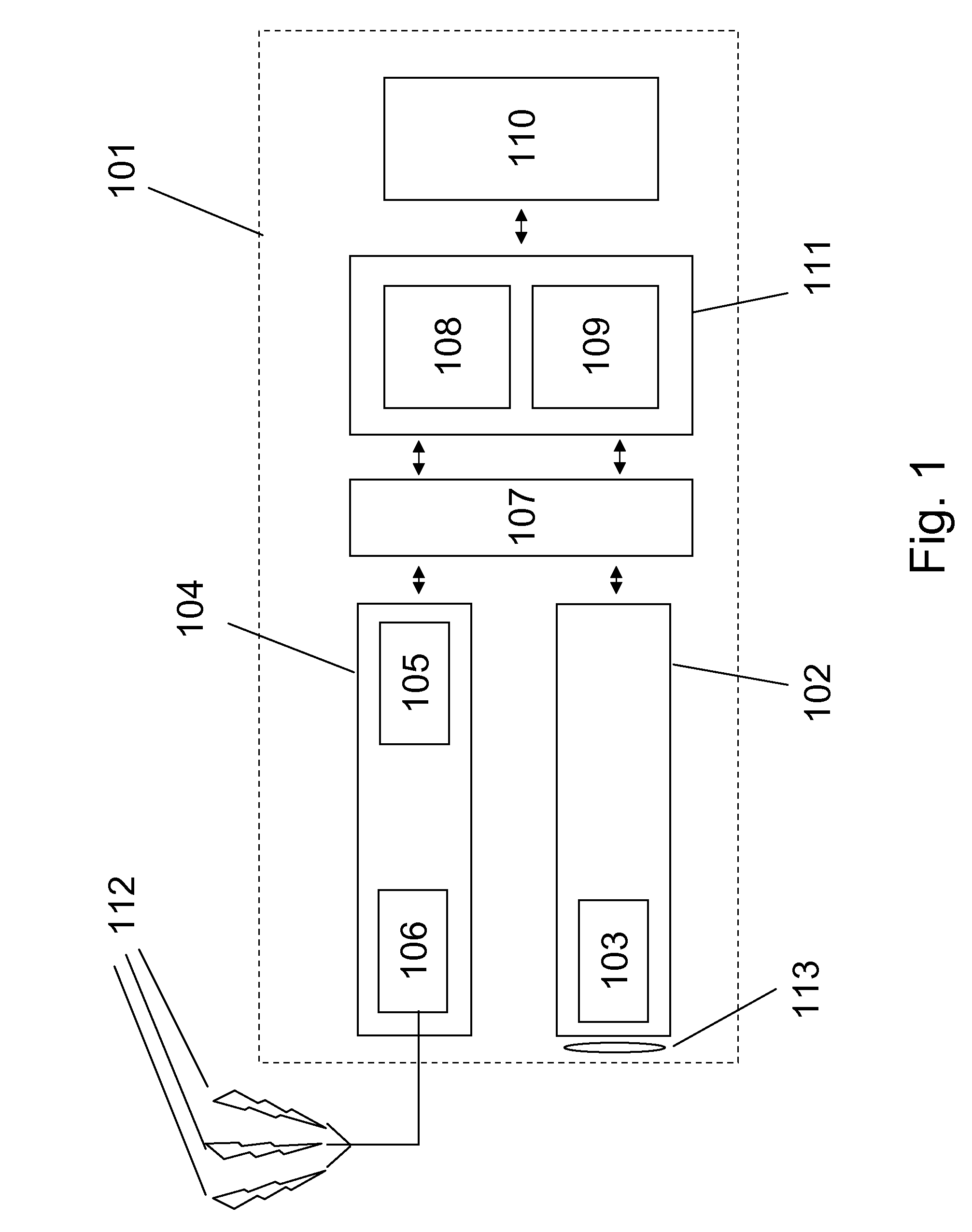
[0028]The present invention refers to a navigation system and a related navigation method running on a portable device or host system 101 as described on FIG. 1. The host system 101 contains a GNSS receiver 104, preferably a GPS receiver 104 integrating an RF front-end 106 receiving navigation signals 112 sent by satellites, and a GNSS processor 105. The GNSS receiver 104 can be a module in a cellular phone, a PDA (Portable Digital Assistant) and so forth; however it can also consist in a pluggable module, which may be connected to the hosting device 101 by means of an appropriate bus, for example a GPS PC-card.

[0029]According to the preferred embodiment illustrated on FIG. 1, the “GPS receiver”104 is coupled to a camera module 102 of the host system through a communication interface 107. The camera module 102 is depicted with its lens 113; it also contains a sensor 103, for example a CCD image sensor or a CMOS image sensor.

[0030]The interface 107 is not only meant for the connectio...


PUM


Abstract

A method of computing navigation information in a portable device comprising a GNSS receiver arranged to receive navigation signals from a plurality of navigation satellites, and a GNSS processor to extract a GNSS position information from said navigation signals. The GNSS receiver is also arranged to obtain image data from a camera module. The method comprises the steps of: deriving a set of position information from the camera module; providing the camera-derived position information to a navigation processor; using said set of camera-derived position information and said navigation signals, to generate a position fix of the GNSS receiver; computing navigation information based on said generated position fix.

Description

FIELD OF THE INVENTION[0001]The present invention relates to a portable signal radiolocalization receiver integrated into another host system, like for example a general-purpose computer, PDA or cell phone, which uses data provided by a camera in order to help the localization process.DESCRIPTION OF RELATED ART[0002]The global navigation satellite systems (GNSS), such as GPS (Global Positioning System), GLONASS or Galileo rely on the reception of radio signals broadcast from a number of orbiting satellites and use the information contained in these signals to determine the distances, or ranges, from the receiver to each of the received satellites. The orbits of the satellites being known, absolute time and the location of the GPS receiver can then be determined geometrically.[0003]As opposed to the GNSS radiolocalization system, inertial navigation systems (INS) have been developed in order to provide positioning information in a standalone manner, based on embedded sensor informati...

Claims


Application Information

Patent Timeline
Patent Type & Authority Applications(United States)
IPC IPC(8): G01C21/00G01S19/47G01C21/12G01S5/14G01S19/48
CPCG01S19/48G01S19/485G01C21/28
Inventor BUROS, JULIEN
Owner QUALCOMM INC
Why Eureka
Try Eureka