High-speed electric system

a high-speed electric system and electric motor technology, applied in the direction of vacuum cleaners, synchronous motor starters, sport apparatus, etc., can solve the problems of increasing the cost of the electric system, and increasing the difficulty of driving current, so as to simplify the assembly of the electric machine, reduce the cost of the electric system, and ensure the effect of constant output power

Active Publication Date: 2010-10-07
DYSON TECH LTD
View PDF58 Cites 40 Cited by
  • Summary
  • Abstract
  • Description
  • Claims
  • Application Information

AI Technical Summary

Benefits of technology

[0014]The range of excitation voltages may extend between a minimum voltage and a maximum voltage, and the minimum voltage is less than 80% of the maximum voltage level. This then represents a relatively broad range of voltages over which constant output power and/or good efficiency

Problems solved by technology

It therefore becomes increasingly difficult to drive current and thus power into the phase winding.
Additionally, in a single-phase machine rotor losses are gen

Method used


Image

  • High-speed electric system
  • High-speed electric system
  • High-speed electric system

Examples


Embodiment Construction

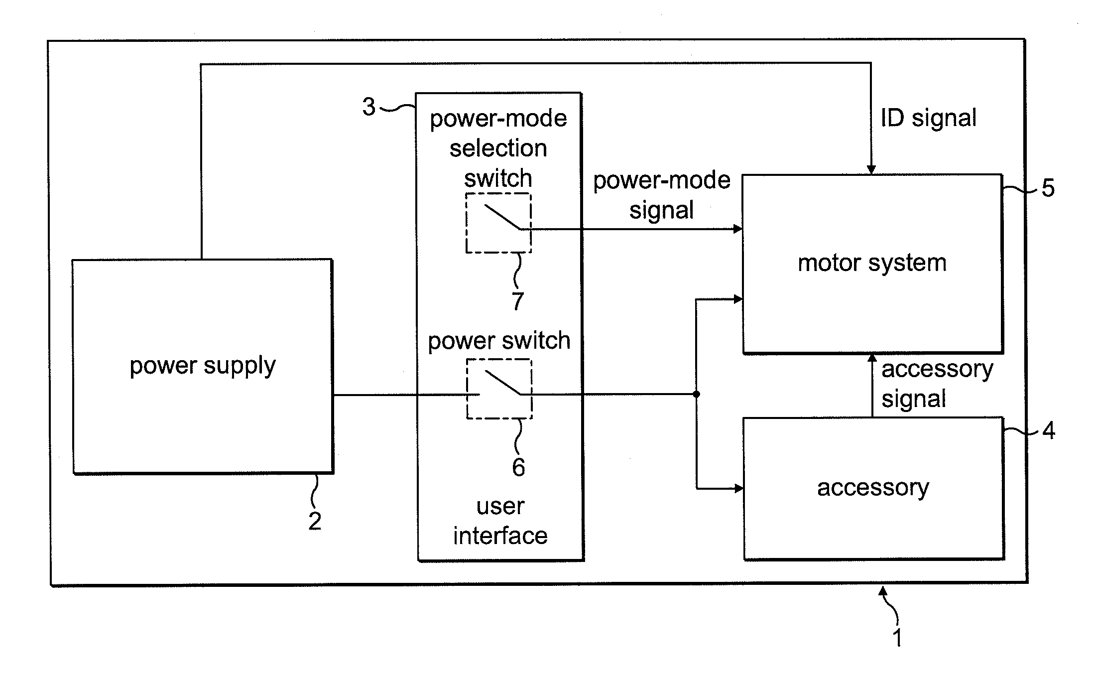
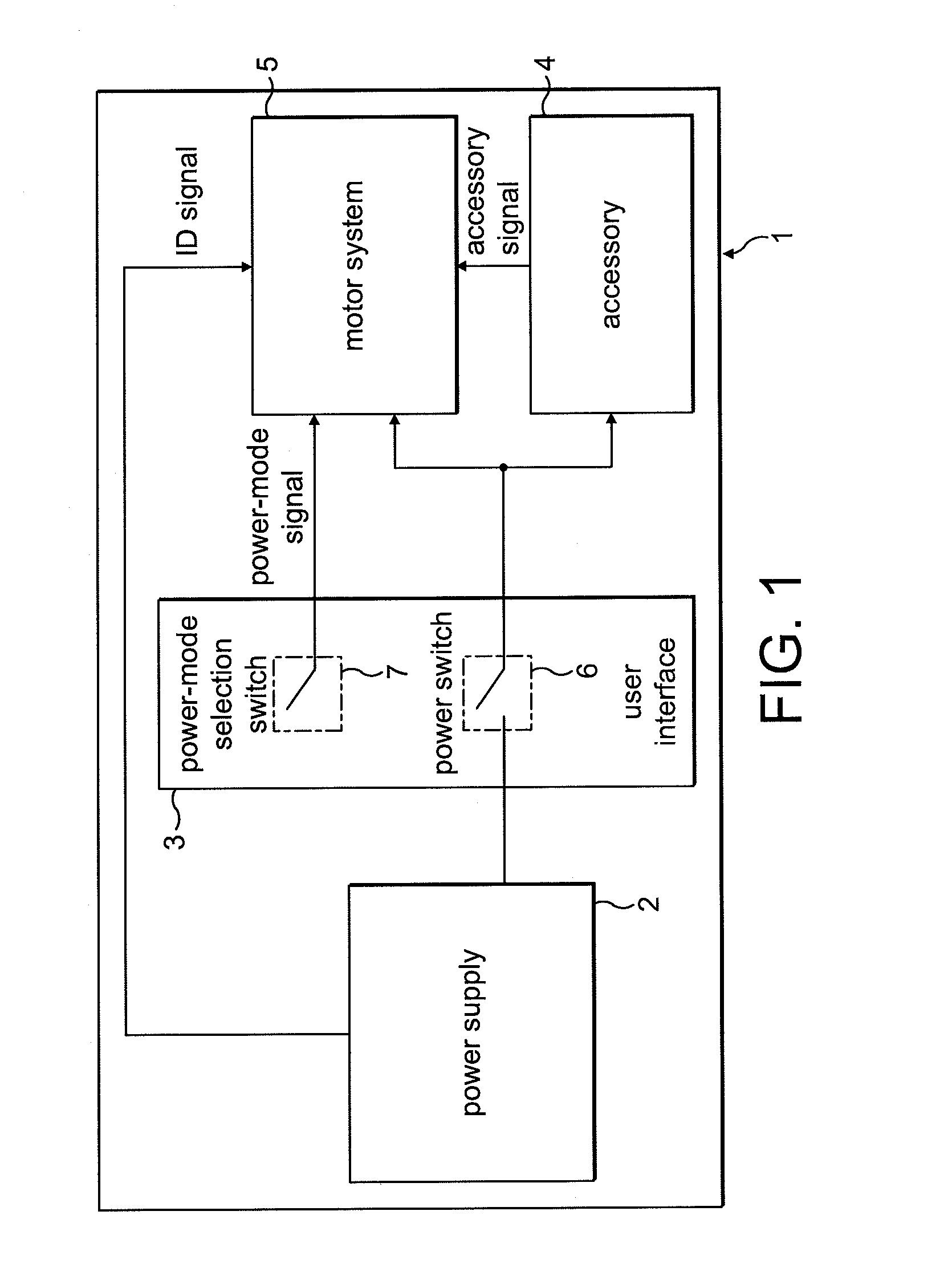
[0028]The product 1 of FIG. 1 comprises a power supply 2, a user interface 3, an accessory 4, and a motor system 5.

[0029]The power supply 2 comprises a battery pack that supplies a DC voltage to both the accessory 4 and the motor system 5. The power supply 2 is removable from the product 1 such that the product 1 may be used with different battery packs. For the purposes of the present description, the power supply 2 is either a 4-cell battery pack providing a 16.4 V DC supply or 6-cell battery pack providing a 24.6 V DC supply. In addition to providing a supply voltage, the power supply outputs an identification signal that is unique to the type of battery pack. The ID signal takes the form of a square-wave signal having a frequency that varies according to the type of battery pack. In the present example, the 4-cell battery pack outputs an ID signal having a frequency of 25 Hz (20 ms pulse length), while the 6-cell battery pack outputs an ID signal having a frequency of 50 Hz (10 ...


PUM


Abstract

An electric system that includes a single-phase permanent-magnet electric machine and a control system for driving the electric machine under load at speeds in excess of 60 krpm. Additionally, a product that includes the electric system.

Description

REFERENCE TO RELATED APPLICATIONS[0001]This application claims the priority of United Kingdom Application No. 0905919.7, filed Apr. 4, 2009, the entire contents of which are incorporated herein by reference.FIELD OF THE INVENTION[0002]The present invention relates to a constant-power electric system.BACKGROUND OF THE INVENTION[0003]The present invention relates to a high-speed electric system and in particular to a system comprising a single-phase permanent-magnet electric machine.[0004]Single-phase, permanent-magnet electric machines are driven by commutating current in a single phase winding. As the speed of the electric machine increases, the back emf in the phase winding increases. It therefore becomes increasingly difficult to drive current and thus power into the phase winding. Additionally, in a single-phase machine rotor losses are generally high due to armature reaction disturbing the field in the magnet. Accordingly, high-speed systems generally comprise an electric machin...

Claims


Application Information

Patent Timeline
IPC IPC(8): A47L9/22H02P6/08H02K1/08H02K21/18H02P27/08
CPCA47L5/24A47L9/0411A47L9/2831A47L9/2847A47L9/2884Y02B40/82H02P6/008H02P6/085H02P6/145H02P29/026A47L9/2889H02P6/26H02P6/153Y02B40/00H02P6/15H02K21/12H02K29/08
Inventor CLOTHIER, ANDREW CHARLTON
Owner DYSON TECH LTD
Why Eureka
Try Eureka