
Integrated Multilayer Insulation

a multi-layer insulation and integrated technology, applied in the field of thermal multi-layer insulation, can solve the problems of reducing the thermal conductivity of the insulation structure, and achieve the effects of reducing the mass of the overall insulation system, minimizing the thermal conduction for the operating conditions, and high performan

Active Publication Date: 2010-10-07
BALL AEROSPACE & TECHNOLOGIES
View PDF38 Cites 64 Cited by
  • Summary
  • Abstract
  • Description
  • Claims
  • Application Information

AI Technical Summary

Benefits of technology

"The present invention provides a high performance integrated thermal insulation (IMLI) structure that includes a plurality of thermal radiation shields, also referred to as sheets. The sheets are made of metalized polymer material, separated by a rigid polymer structure that includes support posts. The structure is designed to minimize thermal conduction for the operating conditions. The insulation performance is not significantly affected by compression effects due to gravity, allowing the low-gravity performance to be better predicted from ground testing. The structure is strong enough to support a thin, lightweight, vacuum shell, which will greatly reduce the mass of the overall insulation system when operation in the atmosphere is required. The use of a rigid polymer structure may also facilitate the automation of the insulation fabrication and the handling of the insulation, reducing labor costs. The polymer structure is arranged so that support posts are comprised of staggered post elements, reducing thermal conductivity of the insulation structure as compared to an embodiment with post elements in each space between adjacent sheets. Beams can be incorporated into the structure to interconnect neighboring support posts. The post elements can be metalized to reduce infrared absorption, and gaps in the metalization can be provided to eliminate conductive paths."

Problems solved by technology

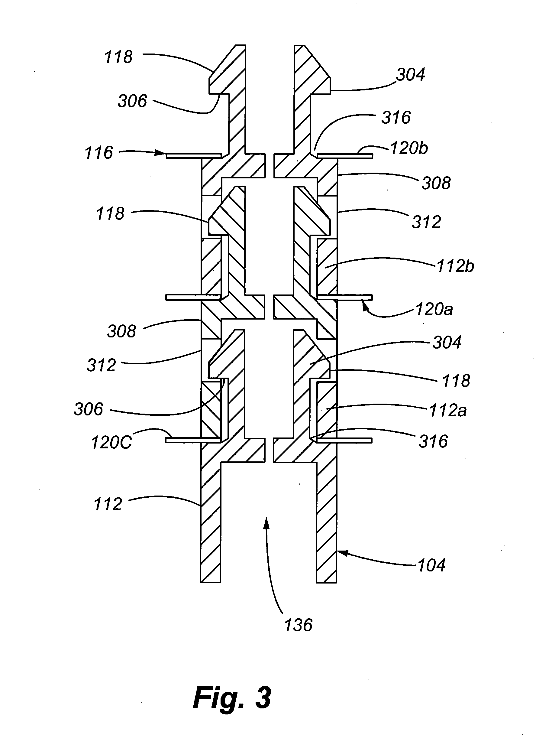
This configuration, which introduces gaps between the individual post elements of the support posts, at least when the IMLI structure is subject to reduced atmospheric pressure, reduces thermal conductivity of the insulation structure as compared to an embodiment with post elements in each space between adjacent sheets.

Method used


Image

  • Integrated Multilayer Insulation
  • Integrated Multilayer Insulation
  • Integrated Multilayer Insulation

Examples


Embodiment Construction

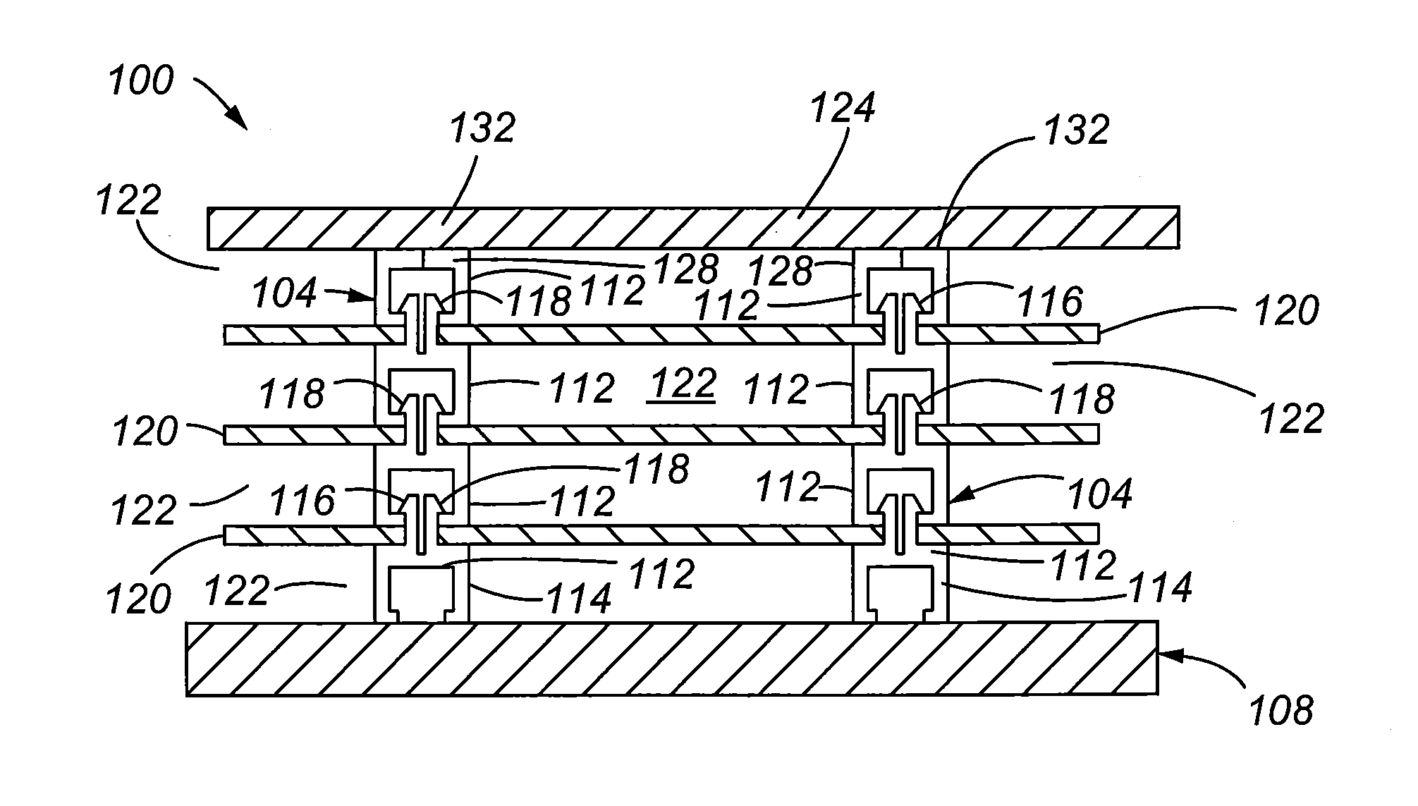
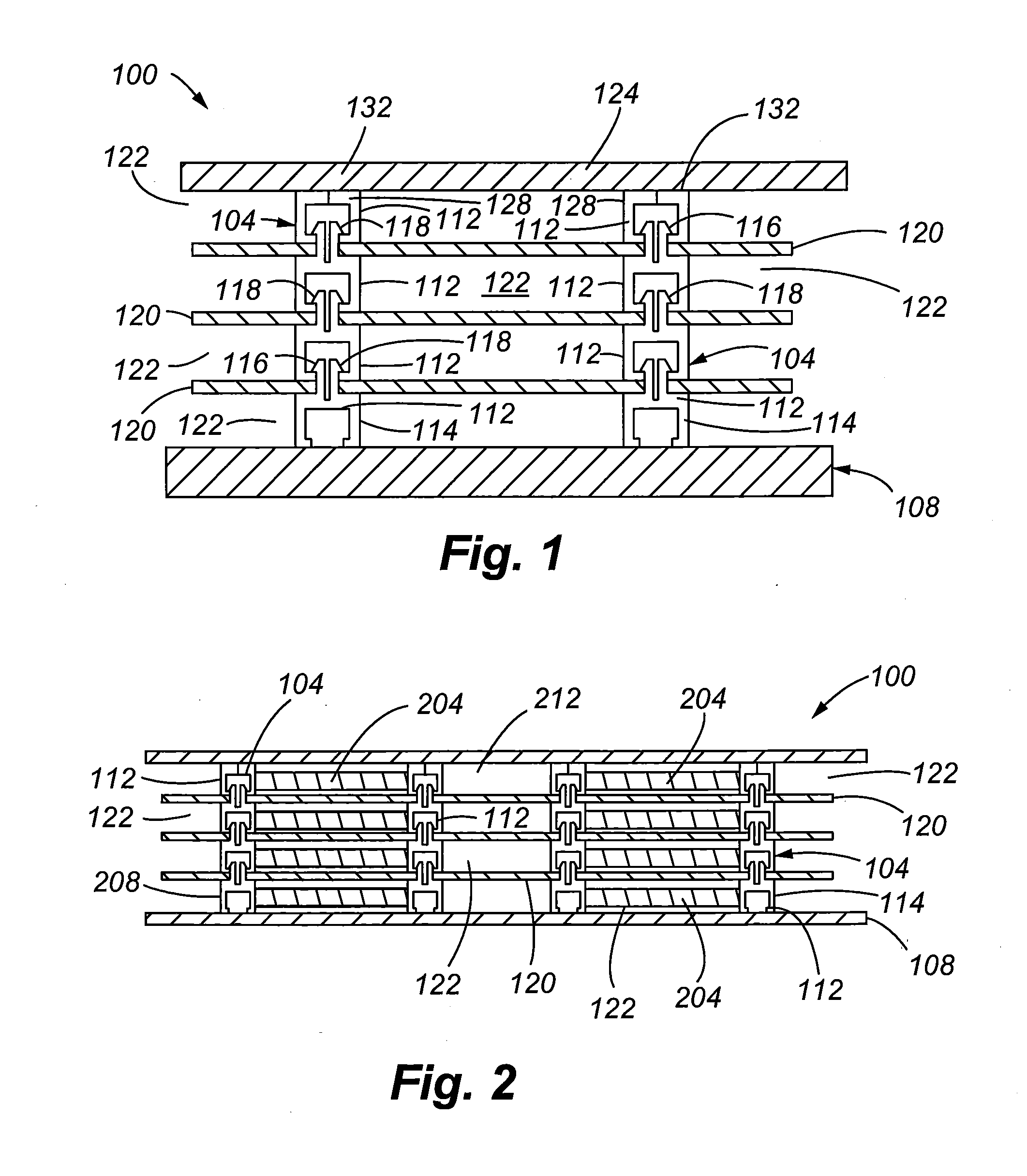
[0024]The present invention is directed to an integrated multilayer insulation (IMLI) structure. As shown in FIG. 1, the IMLI structure 100 in accordance with embodiments of the present invention can include support posts 104 that each comprise a number of post elements 112. The support posts 104 generally support and maintain a space or separation 122 between adjacent thermal radiation shields (also referred to herein as sheets) 120. A base post element 114 in each support post 104 can be bonded or otherwise interconnected to a base structure or layer 108. The base layer 108 can be the radiation shield 120 comprised of the layer of polymer or other material immediately adjacent the item being insulated, or it can be the item being insulated. The support posts 104 can comprise a number of stacked post elements 112. The post elements 112 may be interconnected to one another to form a continuous support post 104 structure using mechanical attachments, fasteners, magnets, an adhesive o...


PUM


Abstract

A multilayer insulation with an array of rigid posts is provided. In particular, the posts are comprised of multiple post elements that are interconnected to radiation shields or sheets comprising the layers of the integrated multi-layer insulation structure. The post elements maintain spacing between adjacent sheets, thus maintaining a volume between the sheets. The post elements within a post can be attached to one another to form an integrated post structure. Moreover, neighboring posts can be interconnected to one another by beams. The post elements can also be configured so that, when the IMLI structure is not subjected to atmospheric pressure, the elements within a post are separated from one another to form gaps, thereby reducing heat transfer between layers.

Description

CROSS REFERENCE TO RELATED APPLICATIONS[0001]This application claims the benefit of U.S. Provisional Patent Application Ser. No. 60 / 895,349, filed Mar. 16, 2007, the entire disclosure of which is hereby incorporated herein by reference.FIELD[0002]The present invention relates generally to thermal multilayer insulation (MLI).BACKGROUND[0003]Multilayer insulation (MLI) is used in applications requiring lightweight, high performance thermal insulation such as spacecraft, cryogenic tanks (dewars), cryogenic refrigerators, and instruments. MLI is typically used in a high vacuum (<10−2 Pascal) where its performance exceeds alternative insulations by a factor of ten. However, the heat flow through the MLI is usually the major heat leak in cryogenic systems, so improvements in thermal performance would be desirable.[0004]In cryogenic space propulsion applications, an insulation system that has high performance on orbit is required. However, the insulation must also provide adequate perfo...

Claims


Application Information

Patent Timeline
Patent Type & Authority Applications(United States)
IPC IPC(8): E04B1/66
CPCB64G1/50Y10T428/239F16L59/065
Inventor MILLS, GARY LOUIS
Owner BALL AEROSPACE & TECHNOLOGIES
Learn More