Refrigeration generation method and system

a technology of refrigeration and generation method, applied in the direction of domestic cooling apparatus, electric generator control, lighting and heating apparatus, etc., can solve the problems of inability to operate inefficiently, complex geared transmission, inability to produce irreversible losses, etc., and achieve the effect of eliminating transmission

Active Publication Date: 2010-10-07
PRAXAIR TECH INC
View PDF18 Cites 13 Cited by
  • Summary
  • Abstract
  • Description
  • Claims
  • Application Information

AI Technical Summary

Benefits of technology

[0016]In either aspect of the present invention, the generator can be a permanent magnet generator directly coupled to the impeller of the turboexpander and the speed of the rotor of the generator and the electrical power is controlled by a variable frequency drive for the permanent magnet generator that can be provided with an input for the setpoint. The use of

Problems solved by technology

However, in the discharge of such products there are thermal losses at the warm end of the main heat exchanger as well as heat leakage into an insulated containment known as a cold box that is used to house the distillation columns.
One problem, however, is that the motor-generator is designed to operate at a maximum nominal 3,600 rpm based upon a line frequency of 60 Hertz and the turboexpander is designed to operate at much higher speeds, typically between 20,000 and 40,000 rpm.
Hence, a c

Method used


Image

  • Refrigeration generation method and system
  • Refrigeration generation method and system
  • Refrigeration generation method and system

Examples


Embodiment Construction

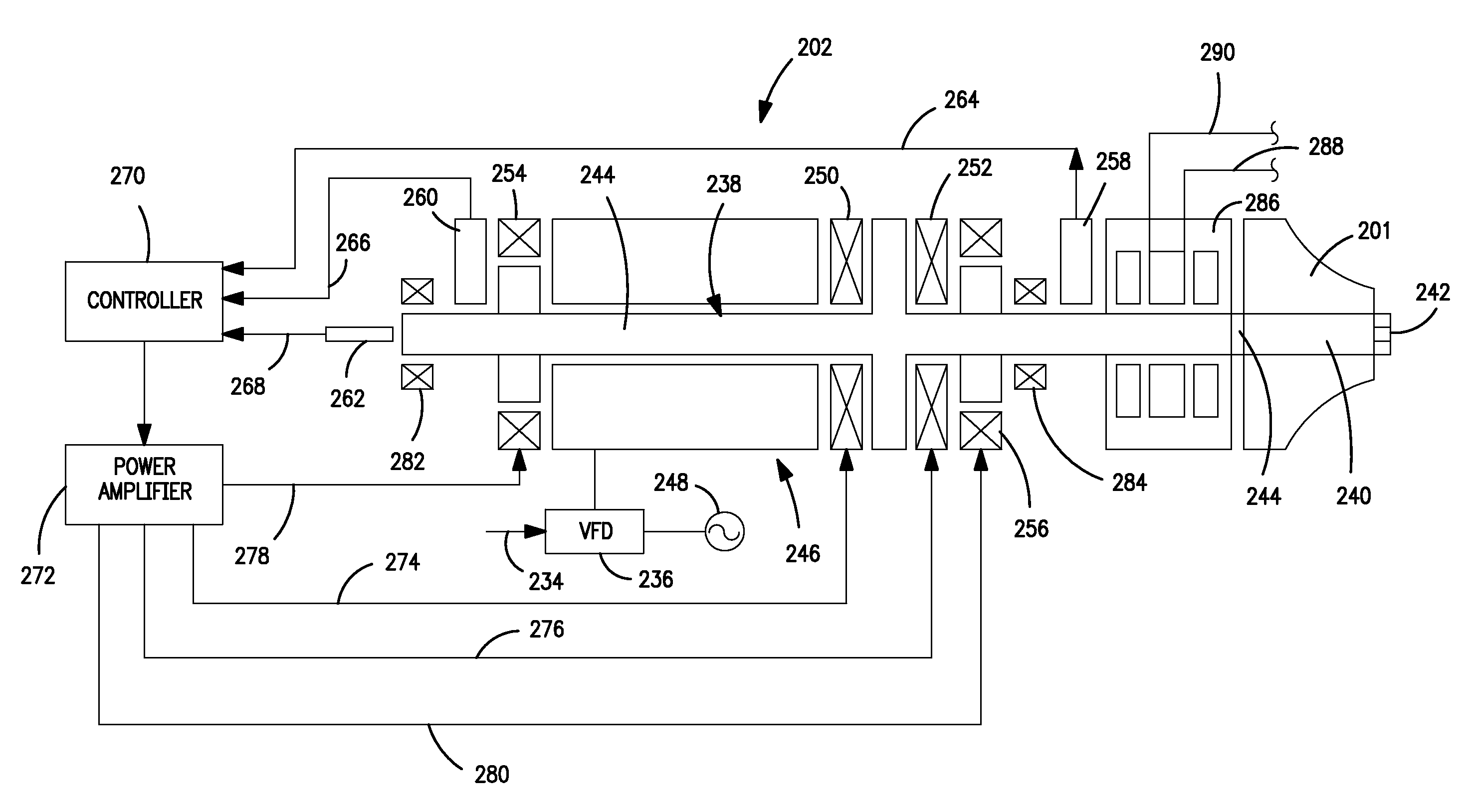
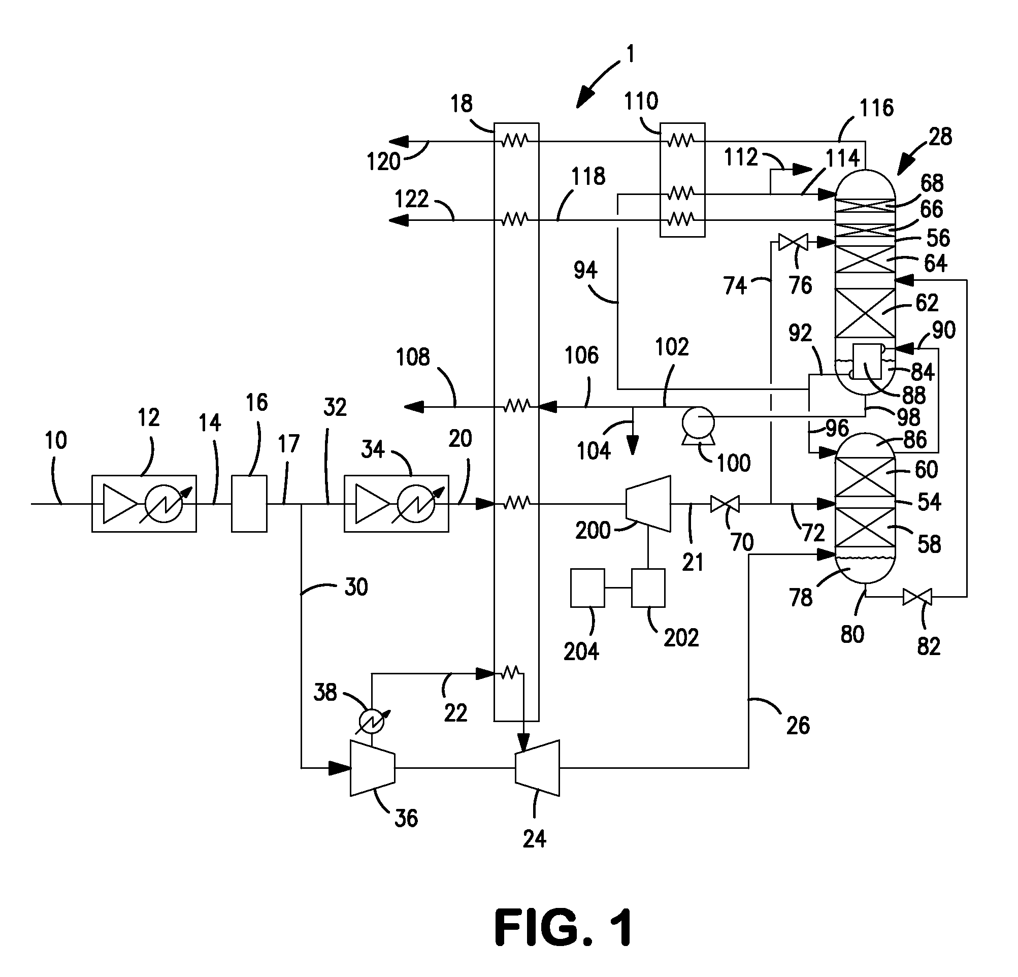
[0023]With reference to FIG. 1, an air separation plant 1 is illustrated that incorporates a refrigeration system that includes a liquid turboexpander 200 coupled to a generator 202 that is controlled in accordance with the present invention as will be discussed in greater detail below. It is understood, however, this is for exemplary purposes to the extent that the subject invention has broader applicability to other types of processes and apparatus that operate at sub-ambient temperatures, for example liquefiers.

[0024]In air separation plant 1, a feed stream 10 containing oxygen and nitrogen, for instance air, is separated by a known cryogenic rectification process to produce gaseous and liquid oxygen products as well as gaseous nitrogen and liquid products.

[0025]Feed stream 10 is compressed within a base load compressor 12 that may be an intercooled, integral gear compressor with condensate removal. The resultant compressed feed stream 14, is then purified within a prepurificatio...


PUM


Abstract

The present invention provides a method and apparatus for generating refrigeration in a process operating at sub-ambient temperatures in which the refrigeration is generated by a turboexpander. The turboexpander is coupled to a generator controlled so that its speed is maintained at a setpoint through electromagnetic braking and its power output is maintained at line matching voltage and frequency. The speed control of the generator therefore, also controls the speed of the turboexpander. The setpoint is calculated to be equal to a product of an operational efficiency parameter, U/Co, and a square root of twice the enthalpy drop in the flow passing through the turboexpander divided by a product of pi and a diameter of an impeller employed within the turboexpander.

Description

FIELD OF THE INVENTION [0001]The present invention relates to a method and apparatus for generating refrigeration in a process operating at a sub-ambient temperature in which the refrigeration is generated by a turboexpander and the work of expansion is converted to electrical power by a variable speed generator coupled to the turboexpander. More particularly, the present invention relates to such a method and system in which an auxiliary controller computes an efficient speed for the turboexpander and such efficient speed serves as an input to a speed controller associated with the variable speed generator to control the speed of the generator and therefore the turboexpander by electromagnetic braking.BACKGROUND OF THE INVENTION [0002]Refrigeration is generated in sub-ambient temperature apparatus such as air separation plants and liquefiers to produce the necessary sub-ambient temperatures required for the operation of such apparatus. The refrigeration is generated by expanding a ...

Claims


Application Information

Patent Timeline
IPC IPC(8): F25J3/00F25B11/02F25D9/00
CPCF25J3/0409F25J3/04296F25J3/04387F25J3/04412F25J2240/42F25J3/04866F25J2240/10F25J2240/30F25J3/04781F25J2280/02
Inventor RAUCH, JEREMIAH JAMESBAKER, ROBERT LEROYO'CONNOR, GERALD T.STANKO, MICHAEL JOHNCHINTA, MURALI
Owner PRAXAIR TECH INC
Why Eureka
Try Eureka