Two-phase-flow, panel-cooled, battery apparatus and method

a battery pack and panel cooling technology, applied in lighting and heating apparatus, semiconductor devices, solid-state devices, etc., can solve the problem of limited convection on very short paths, and achieve the effect of enhancing the free convection of liquids and vapors

Inactive Publication Date: 2010-10-07
BATTY J CLAIR +1
View PDF3 Cites 30 Cited by
  • Summary
  • Abstract
  • Description
  • Claims
  • Application Information

AI Technical Summary

Benefits of technology

[0012]In alternative embodiments, the housing may be a sealed container having electrical components deployed on planar substrates, such as electronic components mounted on a printed circuit board, plates of a lithium-ion battery, or plates of some other battery system. The substrates may typically be arranged in banks or batteries of parallel, planar, walls with the working fluid free to pass completely around the components and substrates in intimate contact. For example, a dielectric coolant may eliminate the need for discrete panels to carry heat away from heat sources. Thus, the operational descriptions herein regarding enclosed, sealed panels, may be said, and is intended to apply, to banks of panels sealed in a single housing surrounding the entire bank or battery of heating panels.
[0013]Even concentric cylinders around cylindrical batteries can create the operation of bubble-scrubbing, enhancing free convection of liquids and vapors in a narrow channel.

Problems solved by technology

Conduction may be limited to very short paths.

Method used


Image

  • Two-phase-flow, panel-cooled, battery apparatus and method
  • Two-phase-flow, panel-cooled, battery apparatus and method
  • Two-phase-flow, panel-cooled, battery apparatus and method

Examples


Embodiment Construction

[0040]It will be readily understood that the components of the present invention, as generally described and illustrated in the drawings herein, could be arranged and designed in a wide variety of different configurations. Thus, the following more detailed description of the embodiments of the system and method of the present invention, as represented in the drawings, is not intended to limit the scope of the invention, as claimed, but is merely representative of various embodiments of the invention. The illustrated embodiments of the invention will be best understood by reference to the drawings, wherein like parts are designated by like numerals throughout.

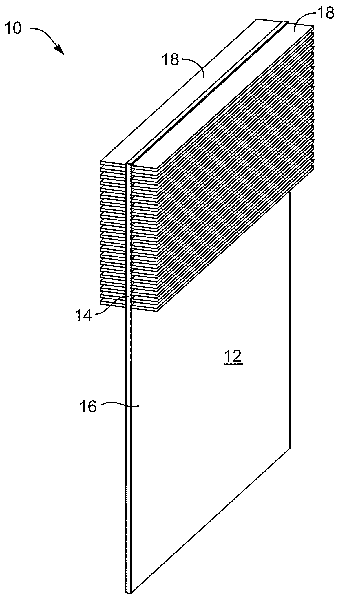
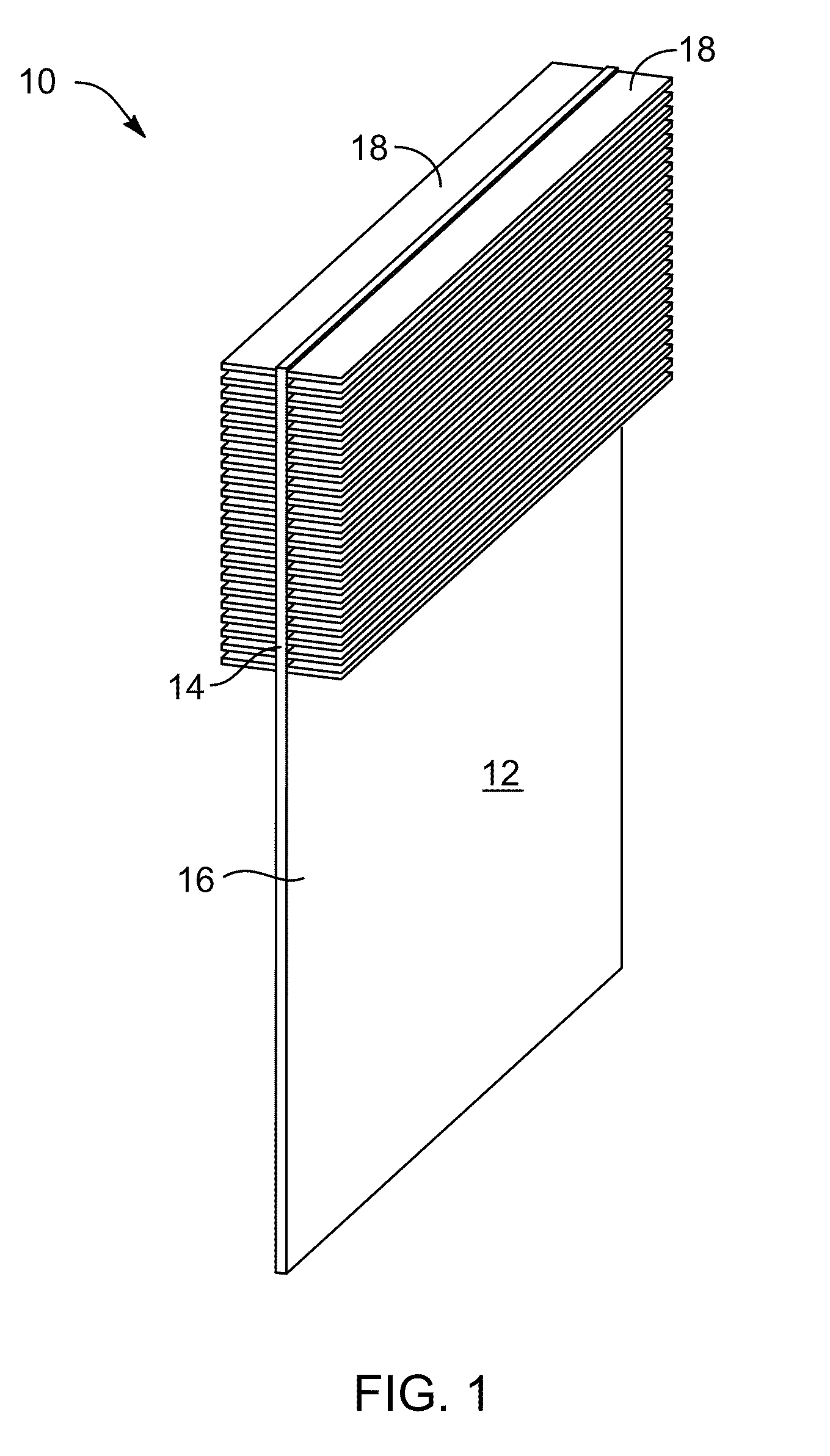
[0041]Referring to FIG. 1, a single (either open-pool, or hermetically sealed) narrow channel may receive heat into a working fluid. The narrow channel in this case may be filled completely or only partially with liquid, allowing for vapor to exit from or to re-condense in an upper portion thereof. Heat generating components may...


PUM


Abstract

Two-phase, boiling heat transfer in confined channels close to a source of heat, such as an electrical component or device, carries the latent heat of vapors away to remote locations where “real estate” demands of air convection are tolerable operationally, economically, and technologically. Liquid-to-vapor, phase-change, heat transfer in a narrow channel (e.g., typically less than 0.200 inches total thickness, and often less than 0.150 in the channel itself) improves by several hundred percent the heat extraction from modest temperature (e.g., about 120 degree F.) devices, when compared to heat fluxes in pool boiling. Saturated working fluids provide nearly isothermal conditions in the working fluid. Minimal conduction paths provide minimal temperature gradients, and capillary action may maintain nearly constant temperature conditions about a surface of a heat source, while carrying heat of vaporization away to a condensation location.

Description

RELATED APPLICATIONS[0001]This patent application claims the benefit of U.S. Provisional Patent Application Ser. No. 61 / 167,019, filed: Apr. 6, 2009 and entitled TWO-PHASE-FLOW, PANEL-COOLED, BATTERY APPARATUS AND METHOD, which is incorporated herein by reference. Also, this patent application incorporates herein by reference U.S. patent application Ser. No. 11 / 743,555, filed on May 2, 2007 and U.S. patent application Ser. No. 12 / 417,552, filed on Apr. 2, 2009.BACKGROUND[0002]1. The Field of the Invention[0003]This invention relates to heat transfer and, more particularly, to novel systems and methods for two-phase cooling of battery packs using comparatively modest temperature differentials.[0004]2. The Background Art[0005]A drawback and technical limitation of high-density populations of electronic components and chips is the difficulty of cooling. Electrical processes reject heat that must be carried away. With greater integration of electronic components, heat rejection cannot b...

Claims


Application Information

Patent Timeline
Patent Type & Authority Applications(United States)
IPC IPC(8): F28D15/02
CPCF28D15/0233F28D15/0266F28F23/00H01L23/427H01M10/0525H01M10/5004H01L2924/0002H01M10/5046H01M10/5048H01M10/5079H01L2924/00H01M10/613H01M10/6551H01M10/6552H01M10/6569Y02E60/10
Inventor BATTY, J. CLAIRRUSCH, BLAKE
Owner BATTY J CLAIR
Why Eureka
Try Eureka