Method for improved brittle materials processing

a technology of brittle materials and laser processing, which is applied in the direction of lasers, manufacturing tools, welding/soldering/cutting articles, etc., can solve the problems of difficult to precisely separate parts, difficult to apply cited approaches, and difficult to precisely apply them, so as to avoid chipping and cracking, and avoid excessive heat buildup in the region

Inactive Publication Date: 2010-10-07
ELECTRO SCI IND INC
View PDF33 Cites 63 Cited by
  • Summary
  • Abstract
  • Description
  • Claims
  • Application Information

AI Technical Summary

Benefits of technology

[0005]An aspect of the instant invention is a method for laser machining complex trajectories in brittle materials such as glass that avoids chipping and cracking in the material associated with excessive heat build up in the region surrounding the feature without requiring expensive additional equipment or causing a significant reduction if system throughput. Excessive heat build up in the region can be avoided by spacing the laser pulses as the feature is being machined so that succeeding laser pulses do not overlap upon the same location as the previous pulse. An embodiment of the instant invention analyzes the tool path associated with a feature to determine how many passes would be required to laser machine the feature into a workpiece given a desired pulse overlap and step size. A tool path is a series of locations on a workpiece that indicate where a laser pulses are to be directed in order to machine the associated feature. A feature may have multiple possible tool paths depending upon the laser parameters used a...

Problems solved by technology

Such resultant stress and micro cracks either may be sufficient enough to cause the glass fracture and separate along the designed trajectories or may require a subsequent breaking step to separate the glass.
This technology, however, does require a initial mechanical notch to function as a pre-crack.
All these afore-cited approaches are very difficult to apply to the situatio...

Method used


Image

  • Method for improved brittle materials processing
  • Method for improved brittle materials processing
  • Method for improved brittle materials processing

Examples


Embodiment Construction

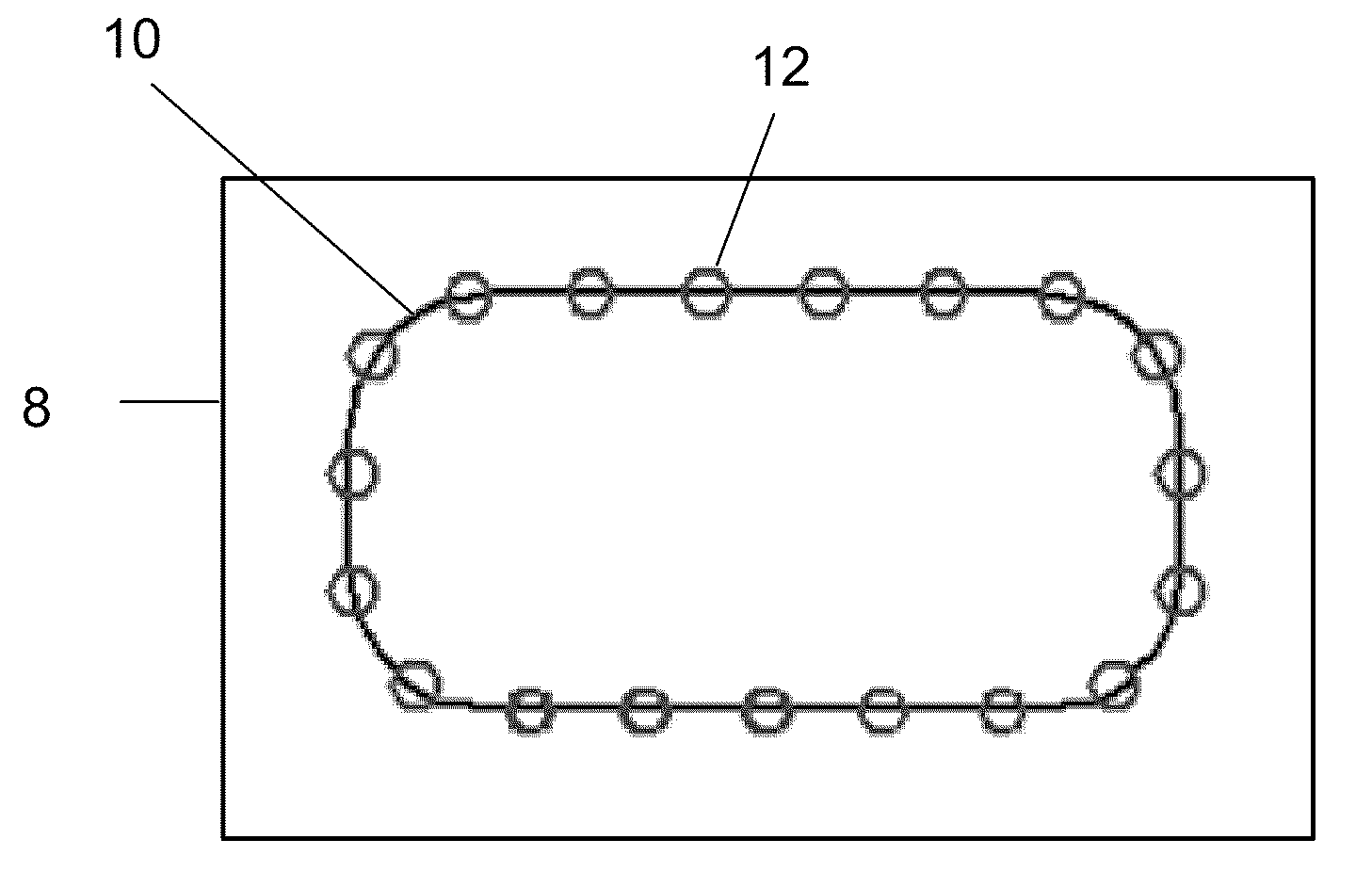
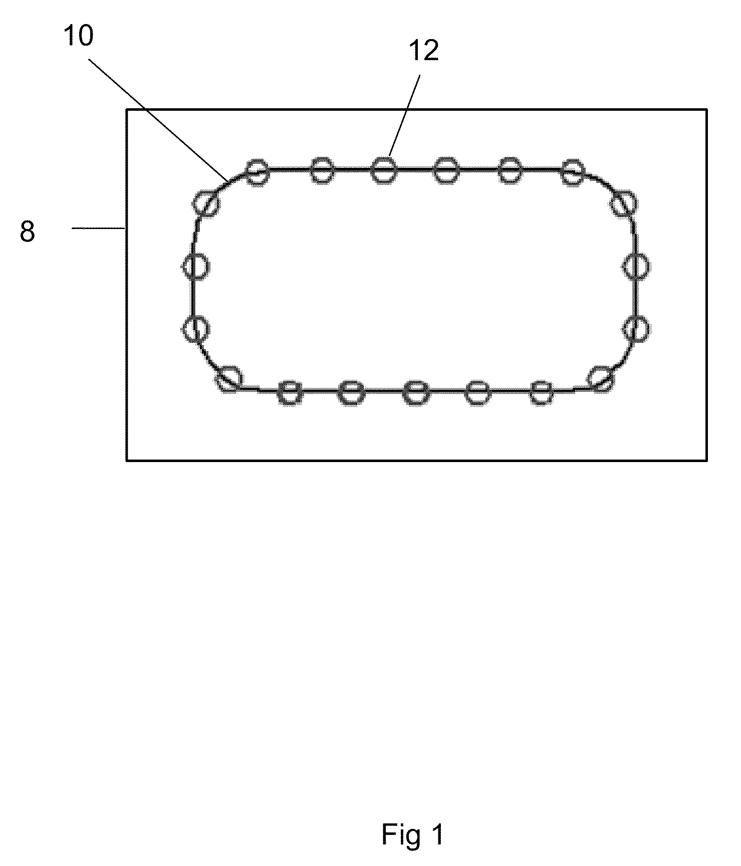
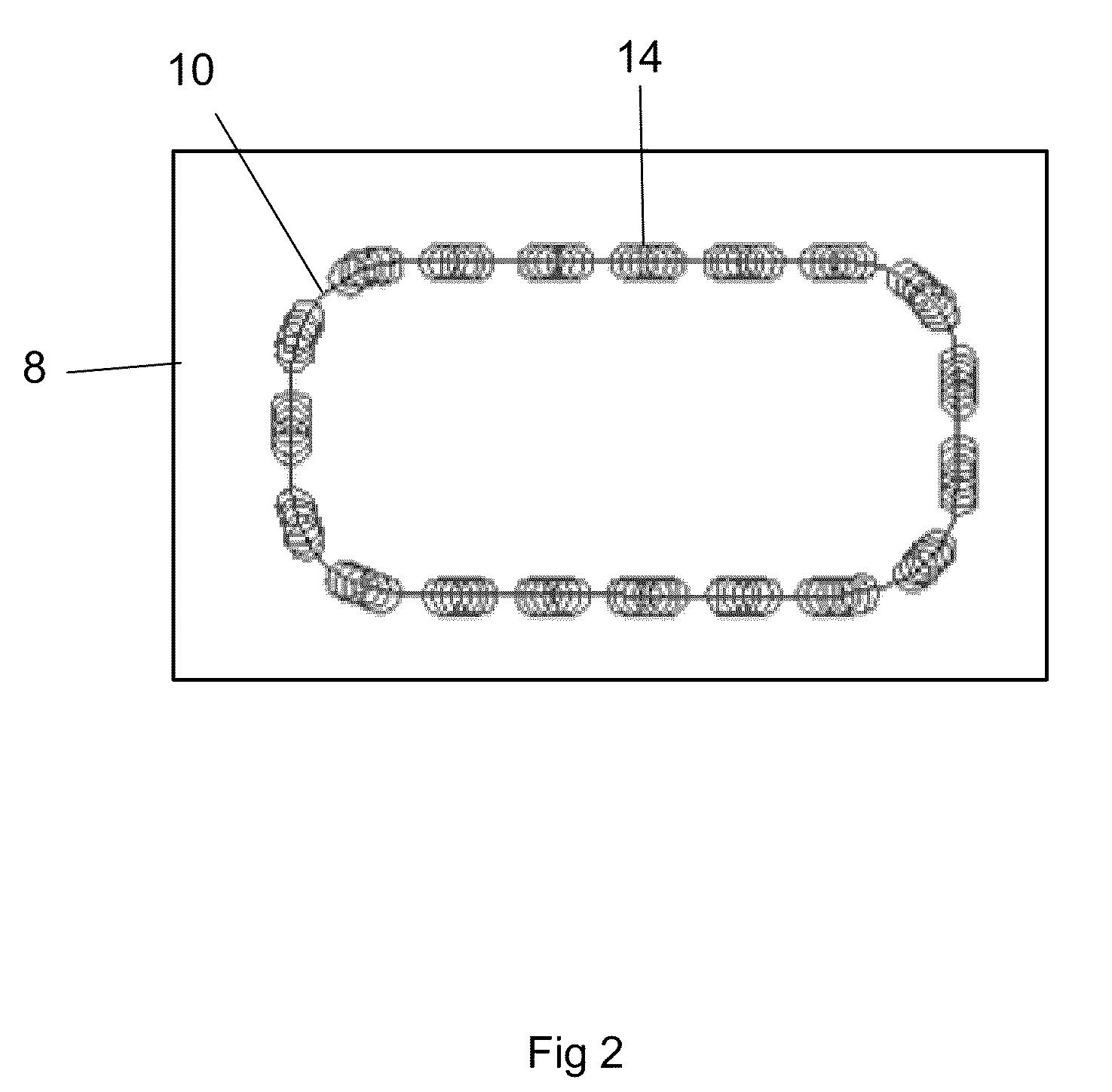
[0010]An embodiment of this invention is an improved method for laser machining a feature in brittle material with a laser processing system. This laser processing system has a tool path, or a series of locations on a workpiece that indicate where a laser pulses are to be directed in order to machine the associated feature. An exemplary laser processing system which may be adapted to embody this invention is the MM5800 manufactured by Electro Scientific Industries, Inc., Portland, Oreg. 97229. This system uses two lasers, one or both of which may be a diode-pumped solid state Q-switched Nd:YAG, or Nd:YVO4 laser operating at wavelengths from about 1064 microns down to about 255 microns at pulse repetition frequencies of between 30 and 70 KHz and having average power of greater than about 5.7 W at 30 KHz pulse repetition rate.

[0011]Embodiments of this invention represent new applications of techniques disclosed in U.S. Pat. No. 7,259,354 METHODS FOR PROCESSING HOLES BY MOVING PRECISEL...


PUM

PropertyMeasurementUnit
Sizeaaaaaaaaaa
Sizeaaaaaaaaaa
Speedaaaaaaaaaa

Abstract

An improved method for laser machining features in brittle materials such as glass is presented, wherein a tool path related to a feature is analyzed to determine how many passes are required to laser machine the feature using non-adjacent laser pulses. Laser pulses applied during subsequent passes are located so as to overlap previous laser spot locations by a predetermined overlap amount. In this way no single spot receives excessive laser radiation caused by immediately subsequent laser pulses being applied adjacent to a previous pulse location.

Description

[0001]This patent application claims benefit of U.S. Provisional Application No. 61 / 164,162, filed Mar. 27, 2009.TECHNICAL FIELD[0002]The present invention regards methods for laser processing of brittle materials such as glass. In more particular it regards methods for laser machining features in glass or like materials while avoiding stress fractures and chipping and maintaining acceptable system throughput.BACKGROUND OF THE INVENTION[0003]Glass cutting has been traditionally realized by using mechanical saws, which scribes the glass and follow with a mechanical breaking step. In recent years, laser technology has been adopted for glass cutting, which generally uses laser as a localized heating source, either accompanied by a cooling nozzle or not, to generate stress and micro cracks along the trajectories to cut the glass. Such resultant stress and micro cracks either may be sufficient enough to cause the glass fracture and separate along the designed trajectories or may require ...

Claims


Application Information

Patent Timeline
IPC IPC(8): B44C1/22B29C35/08
CPCB23K26/4075B23K26/40B23K2103/50B23K26/38B23K26/402B23K26/50H01S3/10
Inventor LEI, WEISHENGSIMENSON, GLENNMATSUMOTO, HISASHILI, GUANGYUHOWERTON, JEFFREY
Owner ELECTRO SCI IND INC
Why Eureka
Try Eureka