Power suppy circuit

a power supply circuit and circuit technology, applied in the direction of electric variable regulation, process and machine control, instruments, etc., can solve the problems of voltage mismatch, large outlay, and distortion of pulse shape,

Inactive Publication Date: 2010-10-07
SIGNIFY HLDG BV +1
View PDF18 Cites 23 Cited by
  • Summary
  • Abstract
  • Description
  • Claims
  • Application Information

AI Technical Summary

Benefits of technology

[0017]This is especially advantageous to drive loads such as LEDs, OLEDs or laser diodes in a pulsed manner, e.g. in display applications. The pre-charged capacitor avoids otherwise necessary rise times at the start of the pulse and thus provides for very exact control, particularly in drive schemes where the voltage level remains constant during a pulse, or where at least the voltage at the end of a pulse is essentially equal to the voltage at the start of the pulse.

Problems solved by technology

However, the corresponding outlay is enormous.
If multiple loads requiring different voltage levels are driven by the same switched mode power supply circuit, or if at least one load requires different voltage levels at different times, then the problem of voltage mismatch may occur: after supplying a first voltage level for a first pulse, the circuit will require some time to supply a different voltage level for a second, following pulse.
This will lead to distortion of the pulse shape and subsequently worsened control results.

Method used


Image

  • Power suppy circuit
  • Power suppy circuit
  • Power suppy circuit

Examples


Embodiment Construction

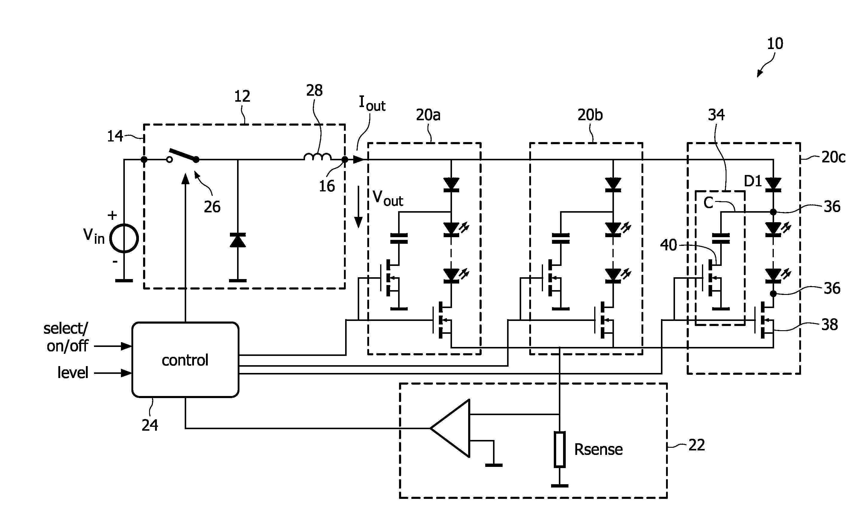
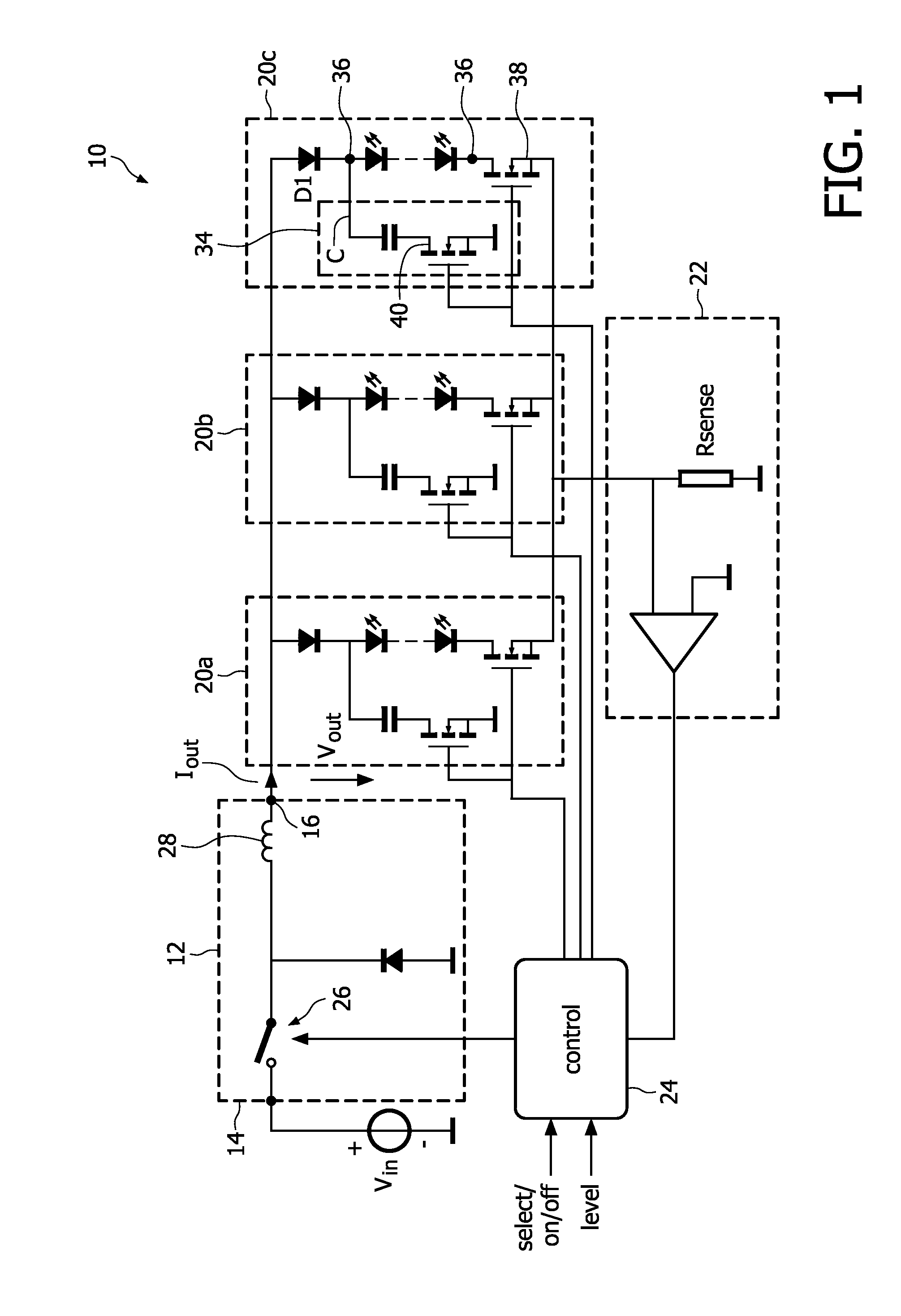
[0044]FIG. 1 shows a circuit diagram of a power supply circuit 10. The circuit 10 comprises a main power supply unit 12 which converts a DC input voltage Vin, received at a voltage input 14 into an output current Iout corresponding to a DC output voltage Vout at an output 16.

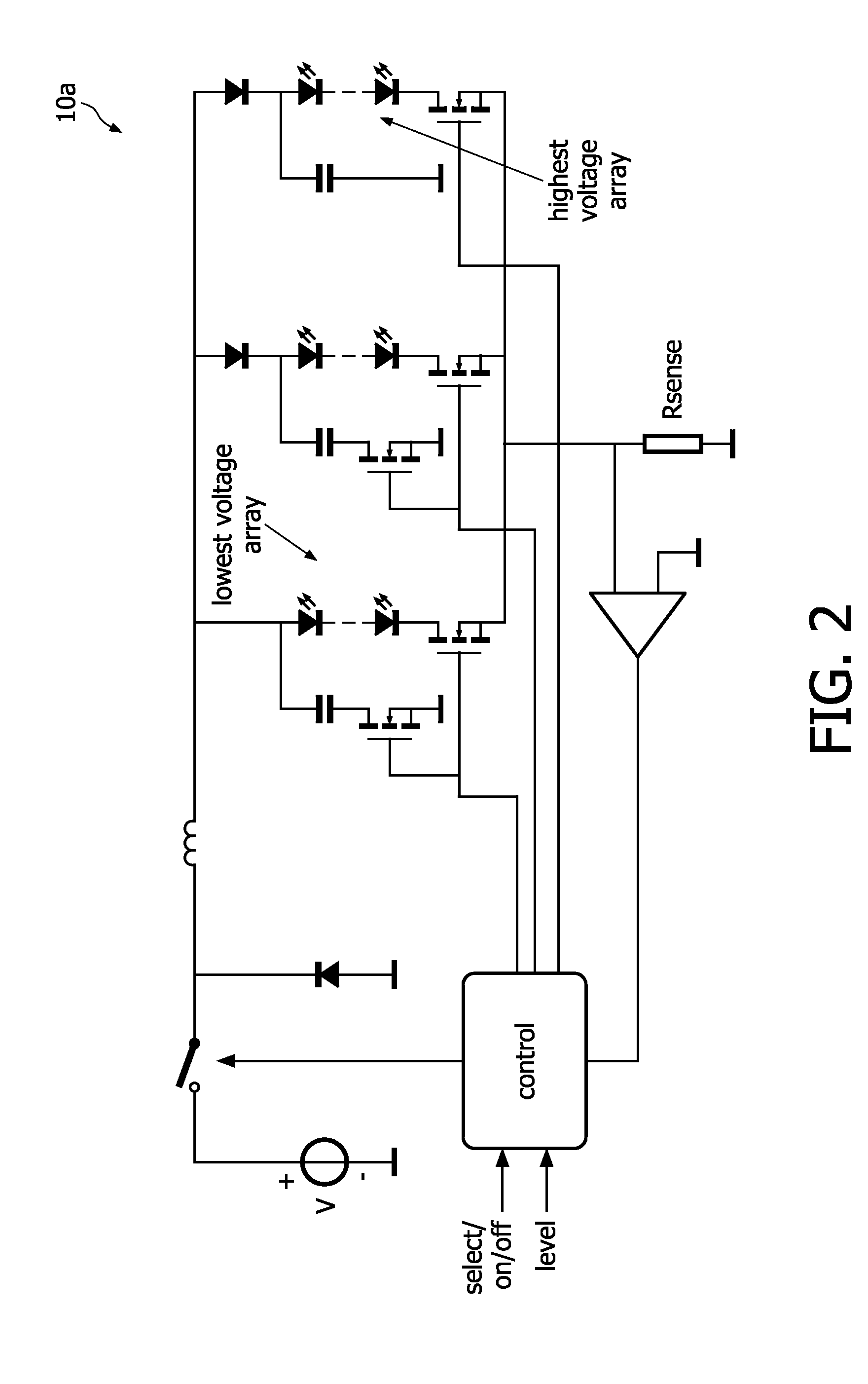
[0045]A plurality of output units—in the shown example three output units 20a, 20b, 20c—are connected in parallel to the voltage output 16 of the power supply unit 12.

[0046]The circuit further comprises a sensing circuit 22 for sensing a current and providing a corresponding feedback signal to a control unit 24.

[0047]The main power supply unit 12 shown in the first example is a buck converter. Alternatively, a different type of switched mode power supply topology could be used, such as a boost converter 12a (FIG. 3), a fly-back converter 12b (FIG. 4) or one of the further known topologies of switched mode converters.

[0048]Within such switched mode converters, there are one or more switches, such as a main switch...


PUM


Abstract

The invention relates to a power supply circuit (10) and methods for supplying electrical power to at least one load output. The circuit comprises a main power supply unit (12) with a voltage input (14), a main switching element (26) and a reactive element (28). The switching element (26) is controllable to deliver an output voltage or current (I out). Output units (20a, 20b, 20c) with load outputs are connected to a main power supply unit (12). In order to drive loads connected to the load outputs, e.g. LEDs, OLEDs or laser diodes, with exact pulses, each output unit (20a, 20b, 20c) has a load switching element (38) to connect or disconnect the main power supply unit (12) to or from the load output. There are further provided switched capacitor units (34), each with a capacitor (C) and a capacitor switching element (40). The capacitor units may be operated such that the capacitors remain essentially charged at different voltage levels. According to a second aspect of the invention, each output unit (20a, 20b, 20c) has a switched capacitor unit (34) with a capacitor (C) and a capacitor switching element (40) connected to the load output. The load switching element (38) and the capacitor switching elements (40) are controlled synchronously.

Description

FIELD OF THE INVENTION[0001]The present invention relates to power supply circuits and methods for supplying electrical power to at least one load output. More specifically, the invention relates to circuits and methods for using a switched mode power supply unit to drive loads in a way that achieves stable, exact current or voltage output well suited e.g. for loads driven in a pulsed manner.BACKGROUND OF THE INVENTION[0002]A plurality of switched mode power supply topologies are known to the skilled person including the buck converter, the boost converter, the fly back converter, the buck boost converter and others. These circuits convert a DC input voltage into a desired output voltage by using at least one main switching element (which may be realized in a plurality of ways, as known to the skilled person, e.g. as a field effect transistor FET) and least one reactive element (i.e. a circuit element which can at least temporarily store energy, usually implemented as an inductor). ...

Claims


Application Information

Patent Timeline
Patent Type & Authority Applications(United States)
IPC IPC(8): G05F1/10H05B41/36H05B44/00
CPCH02M3/155H05B33/0827H05B33/0818H05B45/46H05B45/385H05B45/375H05B45/3725H05B45/38
Inventor OTTE, ROBPEETERS, HENRICUS MARIEVAN DEN BROEK, VINCENT GERARDUS PETRUS CORNELISDEPPE, CARSTEN
Owner SIGNIFY HLDG BV
Why Eureka
Try Eureka