Telecommunication cable equipped with tight-buffered optical fibers

a technology of optical fibers and telecommunication cables, applied in the field of telecommunication cables, can solve the problems of damage to optical fibers, difficult stripping of due lengths, and special tools and installation skills, and achieve the effect of reducing field labor and installation skill

Active Publication Date: 2010-10-07
PRYSMIAN SPA
View PDF8 Cites 36 Cited by
  • Summary
  • Abstract
  • Description
  • Claims
  • Application Information

AI Technical Summary

Benefits of technology

[0008]The Applicant has faced the problem of providing optical cables particularly suitable for riser and horizontal in...

Problems solved by technology

The forces exerted on the fiber during the extraction procedure can damage the optical fiber.
On the other hand, to carry out the connection of the optical fiber to the recipient equipment (e.g. a termination box or the like), the buffer layer shall be peeled off from the optical fiber, and when the buffer layer is tight the stripping of the due length ...

Method used


Image

  • Telecommunication cable equipped with tight-buffered optical fibers
  • Telecommunication cable equipped with tight-buffered optical fibers
  • Telecommunication cable equipped with tight-buffered optical fibers

Examples


example 1

Preparation of a Polymeric Composition

[0064]A polymeric composition were prepared by using the components as shown in Table 1 (the amounts are expressed as % by weight with respect to the total weight of the polymeric composition).

TABLE 1Componentwt %Lotryl ® 17BA0730.2Lotryl ® 30BA027.1Clearflex ® CLB010.1Fusabond ® MC 250D3Hydrofy ® GS 1.547.2Rhodorsil ® GUM 9012Irganox ® 10100.4Lotryl ® 17BA07 (Atofina): copolymer ethylene-butyl acrylate containing 16% to 19% by weight of acrylic ester;Lotryl ® 30BA02 (Atofina): copolymer ethylene-butyl acrylate containing 28% to 32% by weight of acrylic ester;Clearflex ® CLB0 (Polimeri Europa): very low density polyethylene;Fusabond ® MC 250D (DuPont): ethylene-vinyl acetate (28% vinyl acetate);Hydrofy ® GS1.5 (Sima): magnesium hydroxide coated with stearic acid;Rhodorsil ® GUM 901 (Rhodia): dimethylsiloxane, methyl vinyl terminated gum;Irganox ® 1010 (Ciba Specialty Chemicals): phenolic antioxidant.

[0065]The composition were prepared by mixing ...

example 2

Preparation of a Tight Buffer Optical Fiber

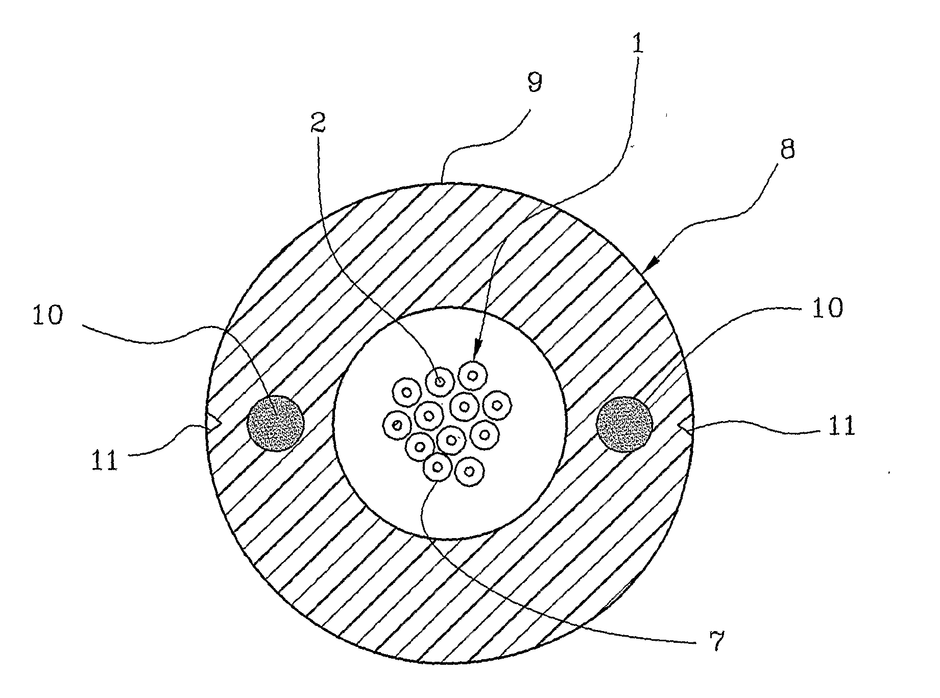
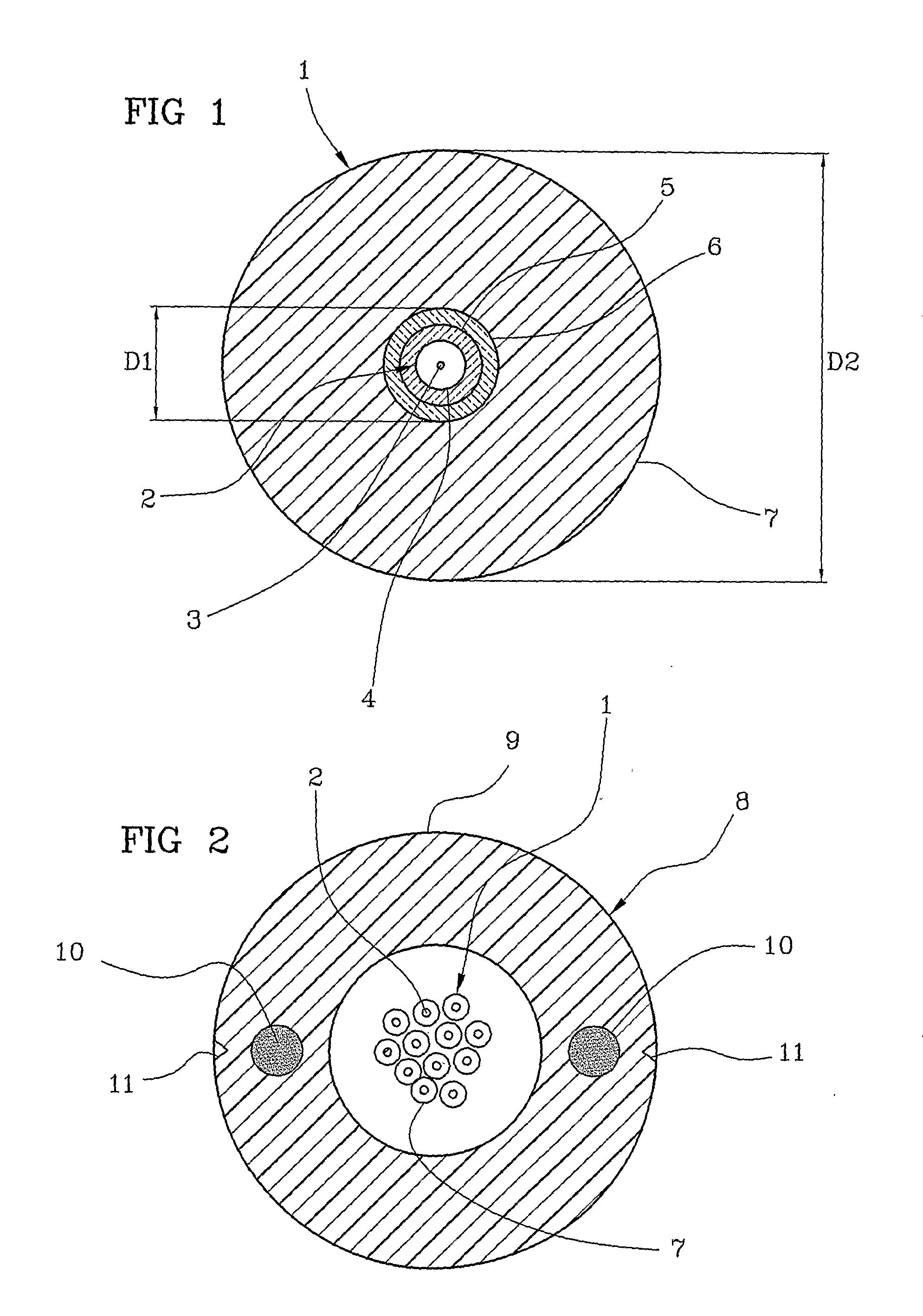
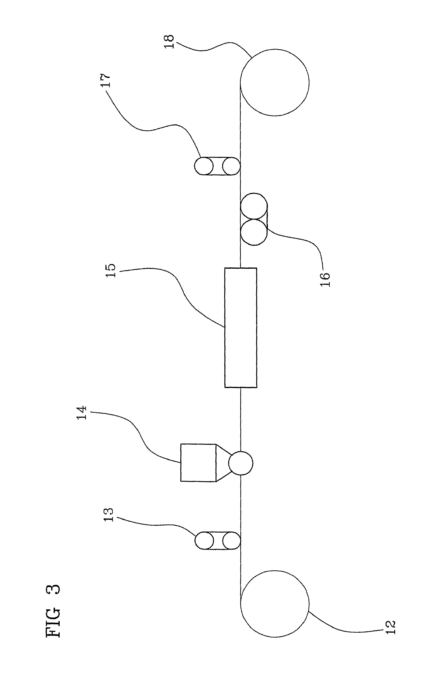
[0073]The polymeric composition as prepared in Example 1 was applied by extrusion onto an optical fiber having an overall diameter of 245±5 μm, with a primary coating having a thickness of 32.5 μm and a secondary coating having a thickness of 27.5 μm.

[0074]The operating conditions of the extruding line were the following:[0075]conic tip inner diameter: 0.45 mm;[0076]conic tip outer diameter: 0.90 mm;[0077]conic die inner diameter: 1.90 mm;[0078]vacuum: −0.1 bar[0079]line speed: 60 m / min;[0080]thermal profile: 125° C. (zone 1), 140° C. (zone 2), 150° C. (zone 3), 160° C. (collar), 165° C. (head);[0081]cooling trough: air at 25° C.;[0082]fibre pay off tension: 100 g[0083]buffered fibre take-up tension: 200 g

[0084]The so obtained buffered optical fiber had an external diameter of 900 μm.

[0085]The following measurements were made on the buffered optical fiber (mean values calculated from nine tested samples):[0086]average strip force: 0.22 N / 15...

example 3

Manual Stripping Test

[0092]Five buffered optical fibers according to the invention coming from different production batches were employed for the test. The buffer layers were manually stripped-off the fibers by the same operator at increasing lengths starting from 10 cm. All of the five optical fibers were easily deprived of the buffer thereof until a length of 50 cm. At a length of 90 cm the buffer of two optical fibers could not be stripped off. For the remaining three, the coherence between buffer and optical fiber (impeding the buffer stripping-off) was reached at 120 cm (two fibers) and 130 cm (one fiber).


PUM

PropertyMeasurementUnit
Temperatureaaaaaaaaaa
Lengthaaaaaaaaaa
Fractionaaaaaaaaaa

Abstract

A telecommunication cable is equipped with at least one optical fiber coated by a tight buffer layer made from a polymeric material having an ultimate elongation equal to or lower than 100% and an ultimate tensile strength equal to or lower than 10 MPa. The above combination of features of the polymeric material forming the buffer layer provides an optical fiber which is effectively protected during installation operations and during use, and at the same time can be easily stripped by an installer without using any stripping tools, simply by applying a small pressure with his fingertips and a moderate tearing force along the fiber axis.

Description

BACKGROUND OF THE INVENTION[0001]The present invention relates to a telecommunication cable equipped with at least one optical fiber. In particular, the present invention relates to a telecommunication cable equipped with at least one tight-buffered optical fiber, especially suitable for indoor installations.[0002]An optical fibre generally comprises a core surrounded by a cladding, said core and cladding being preferably made of glass, and at least one coating. The combination of core and cladding is usually identified as “optical waveguide”. Usually, the coatings of the optical waveguide are two. The coating directly contacting the optical waveguide is called “first coating” or “primary coating”, and the coating overlying the first one is called “second coating” or “secondary coating”. Typically, said first and second coatings are made of a polymeric material, such as a UV-curable acrylate polymer.[0003]Certain applications require the optical fibre to be further coated by a buffe...

Claims


Application Information

Patent Timeline
IPC IPC(8): G02B6/44
CPCC08L23/0853C08L23/0869C08L2203/20C08L2203/202C08L2205/02C08L2205/03G02B6/443G02B6/4402G02B6/4429C08L2666/02
Inventor CONSONNI, ENRICOCESCHIAT, DAVIDE
Owner PRYSMIAN SPA
Why Eureka
Try Eureka