Control system and method for internal combustion engine and engine control unit

a control system and internal combustion engine technology, applied in the direction of electrical control, process and machine control, instruments, etc., can solve the problems of increasing exhaust emissions, affecting the control system, and not being able to configure the above-described control system from the above technical, so as to improve the controllability of the air-fuel ratio, avoid interaction, and high responsiveness

Inactive Publication Date: 2010-10-07
HONDA MOTOR CO LTD
View PDF2 Cites 19 Cited by
  • Summary
  • Abstract
  • Description
  • Claims
  • Application Information

AI Technical Summary

Benefits of technology

[0030]Even more preferably, in the fourth control algorithm, a convergence rate of the output filtered value to the target output value is configured to be lower than a convergence rate of the output value from the oxygen concentration-detecting means to the target output value in the second control algorithm.
[0031]With the configuration of the preferred embodiment, it is possible to avoid interaction between the two control processes executed using the two control algorithms, respectively. In addition to this, in the fourth control algorithm, the convergence rate of the output filtered value to the target output value is set to become lower than the convergence rate of the output value from the oxygen concentration-detecting means to the target output value in the second control algorithm. Therefore, no high responsiveness is required of the variable fresh air amount mechanism, which makes it possible to improve controllability of the air-fuel ratio in a transient state, improve the reduction of exhaust emissions, and prolong the service life of the variable fresh air amount mechanism. Further, since an actuator of the variable fresh air amount mechanism can be downsized, which makes it possible to reduce the weight of the engine, thereby making it possible to improve fuel economy.
[0032]More preferably, in the first control algorithm, when the exhaust system temperature is within the predetermined temperature range, a convergence rate of the exhaust system temperature to the predetermined target temperature is configured to be lower than when the exhaust system temperature is not within the predetermined temperature range.
[0033]With the configuration of the preferred embodiment, as mentioned hereinbefore, the second exhaust gas purification device is configured such that when the exhaust system temperature is within the predetermined temperature range, the second exhaust gas purification device has a higher exhaust gas-purifying capability than when the exhaust system temperature is not within the predetermined temperature range. Therefore, even when the convergence rate of the exhaust system temperature to the predetermined target temperature is configured as described above, it is possible to ensure excellent reduction of exhaust emissions. In addition to this, by lowering the convergence rate of the exhaust system temperature to the predetermined target temperature, the absolute value of the air-fuel ratio parameter correction value can be made smaller, which finally makes it possible to make smaller the absolute value of the target fresh air amount, i.e. the target fuel amount. This makes it possible to reduce the amount of the second fuel, thereby making it possible to improve fuel economy by the reduced amount of the second fuel.
[0034]More preferably, the second exhaust gas purification device has a characteristic of being activated when the exhaust system temperature is within a predetermined activation temperature range, and when the exhaust system temperature is within a temperature range lower than the predetermined activation temperature range, the target air-fuel ratio parameter-calculating means calculates the target air-fuel ratio parameter as a leaner value than when the exhaust system temperature is within the predetermined activation temperature range.
[0035]With the configuration of the preferred embodiment, when the exhaust system temperature is within the predetermined activation temperature range, the target air-fuel ratio parameter is calculated as a richer value than when the exhaust system temperature is within a temperature range lower than the predetermined activation temperature range. This makes it possible to quickly activate the second exhaust gas purification device, thereby making it possible to quickly ensure excellent reduction of exhaust emissions.

Problems solved by technology

However, when the control range of the air-fuel ratio of a combustion air-fuel mixture of the engine is limited, for example, in the case of a diesel engine in which a combustion air-fuel mixture is controlled to a leaner value than the stoichiometric air-fuel ratio, during normal time, it is difficult to continuously control the air-fuel ratio of exhaust gases to a value close to the stoichiometric air-fuel ratio, which can result in increased exhaust emissions.
However, the above-described control system is not configured from the above technical point of view.
Therefore, it sometimes takes a long time for the catalyst temperature to reach the activation temperature range during the start of the engine, and the catalyst temperature sometimes deviates from the activation temperature range during operation of the engine.

Method used


Image

  • Control system and method for internal combustion engine and engine control unit
  • Control system and method for internal combustion engine and engine control unit
  • Control system and method for internal combustion engine and engine control unit

Examples


Embodiment Construction

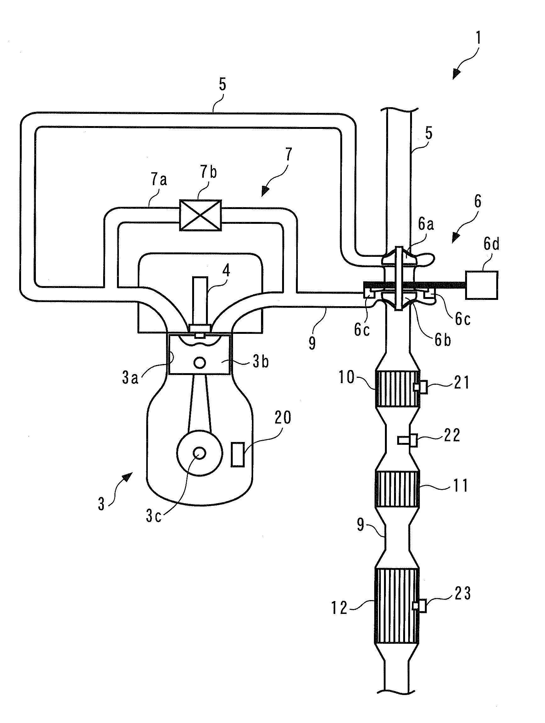
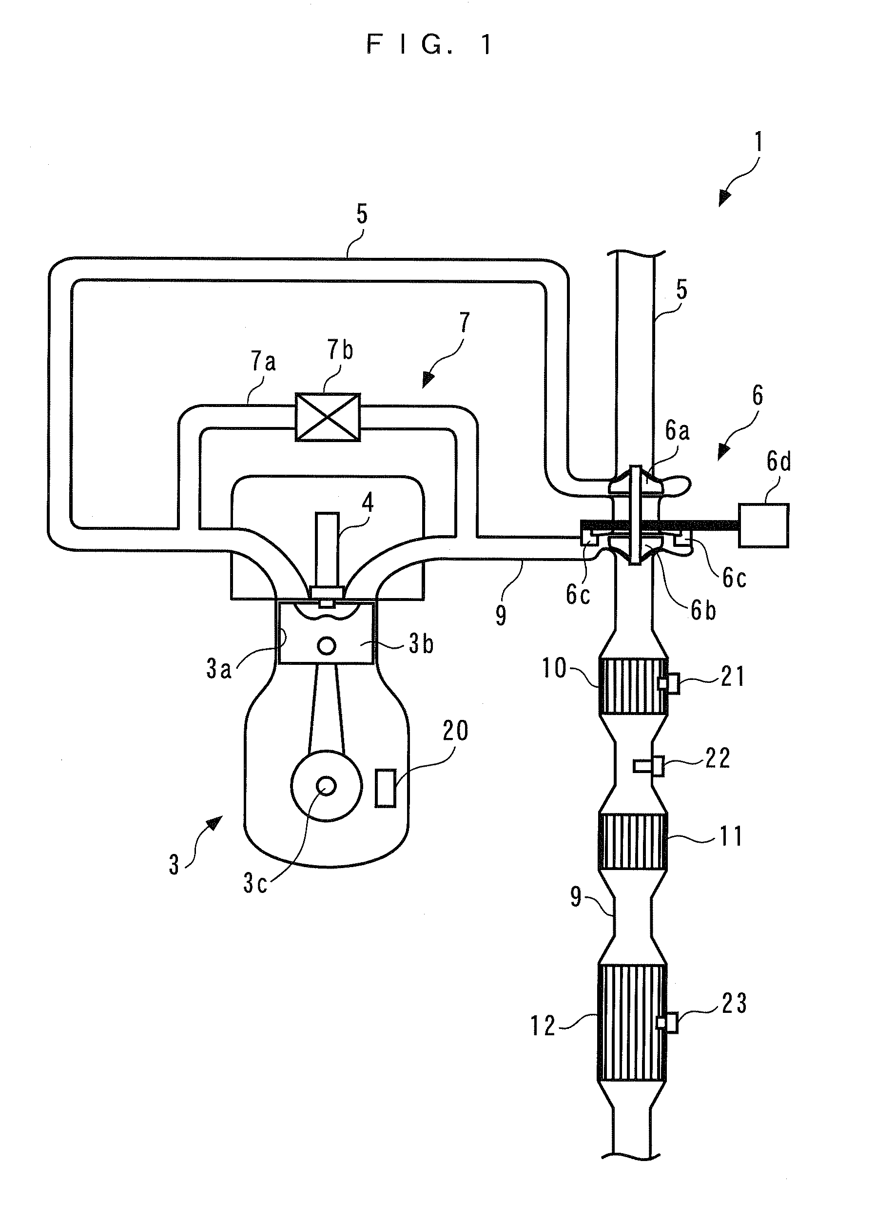
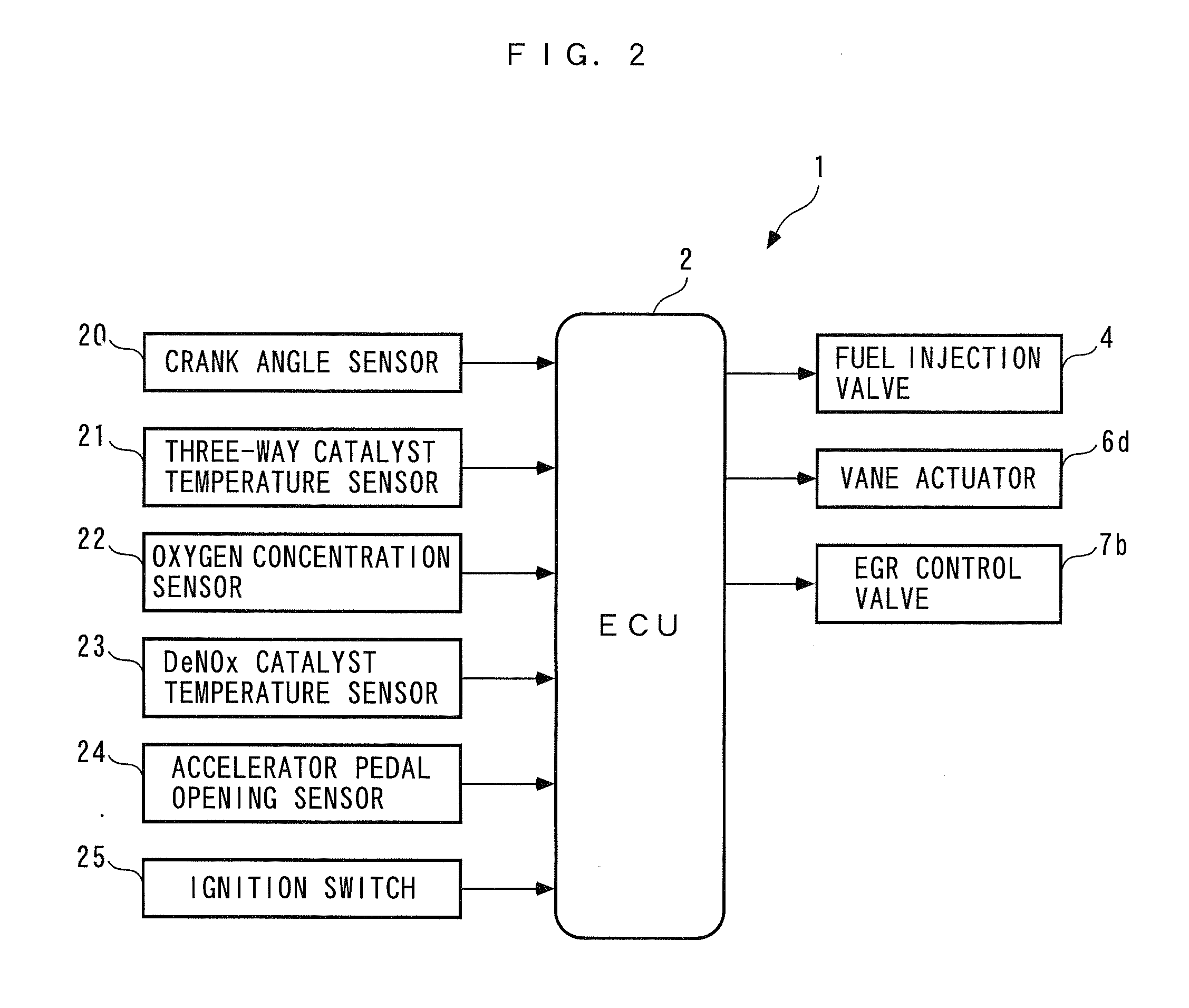
[0097]Hereafter, a control system for an internal combustion engine, according to an embodiment of the present invention will be described with reference to the drawings. FIG. 1 shows the control system 1 according to the present embodiment, and the internal combustion engine (hereinafter referred to as “the engine”) 3 to which is applied the control system. Referring to FIG. 2, the control system 1 includes an ECU 2. As described hereinafter, the ECU 2 carries out various control processes, such as an air-fuel ratio control process, depending on operating conditions of the engine 3.

[0098]The engine 3 is an in-line four-cylinder diesel engine installed on a vehicle, not shown, and includes four pairs of cylinders 3a and pistons 3b (only one pair of which is shown), a crankshaft 3c, and so forth. The engine 3 is provided with a crank angle sensor 20.

[0099]The crank angle sensor 20 is comprised of a magnet rotor and an MRE (magnetic resistance element) pickup, and delivers a CRK signa...


PUM


Abstract

A control system for an internal combustion engine, which is capable of properly controlling both the temperature of an exhaust system and the air-fuel ratio of exhaust gases even when the control range of the air-fuel ratio of a combustion air-fuel mixture is limited, thereby improving the reduction of exhaust emissions. In the control system, a demanded torque-calculating section calculates a demanded torque. A first controller calculates a target equivalent ratio such that a DeNOx catalyst temperature converges to a predetermined target temperature. A second controller calculates three feedback correction values such that an output value from an oxygen concentration sensor converges to a target output value. A third controller calculates a torque fuel injection amount for generating the combustion air-fuel mixture, a post fuel injection amount for supplying unburned fuel to a DeNOx catalyst, etc. based on five values.

Description

BACKGROUND OF THE INVENTION[0001]1. Field of the Invention[0002]The present invention relates to a control system and method for an internal combustion engine having an exhaust system provided with an exhaust gas purification device for purifying exhaust gases, and an engine control unit, which control the temperature of the exhaust system and the air-fuel ratio of exhaust gases.[0003]2. Description of the Related Art[0004]Conventionally, as a control system for an internal combustion engine, the present assignee has already proposed a control system disclosed in Japanese Laid-Open Patent Publication (Kokai) No. H09-273438. This control system is for controlling the air-fuel ratio of exhaust gases flowing through an exhaust passage of the engine. A LAF sensor, an upstream catalyst, an oxygen concentration sensor and a downstream catalyst are arranged in the exhaust passage of the engine from upstream to downstream in the mentioned order. The oxygen concentration sensor detects the c...

Claims


Application Information

Patent Timeline
Patent Type & Authority Applications(United States)
IPC IPC(8): F02D41/00F01N11/00
CPCF02D41/0002F02D41/0007F02D41/0052F02D41/0235F02D41/1401F02D2041/1418F02D41/1446F02D41/1454F02D41/405F02D2041/0265F02D2041/141F02D41/1403
Inventor YASUI, YUJI
Owner HONDA MOTOR CO LTD
Why Eureka
Try Eureka