Friction stir welding tool

a technology of friction stir and welding tool, which is applied in the direction of manufacturing tools, soldering devices, auxillary welding devices, etc., can solve the problems of pin or pins being detachable or broken off from the shank, warping of friction stir welding tools at high welding temperatures, and the shank itself being able to break, so as to achieve the effect of long service li

Inactive Publication Date: 2010-10-14
BOEHLERIT GMBH & CO KG
View PDF10 Cites 62 Cited by
  • Summary
  • Abstract
  • Description
  • Claims
  • Application Information

AI Technical Summary

Benefits of technology

[0019]The geometric embodiment of the friction stir welding tool can be carried out in a similar manner to the prior art, wherein it has been shown that a parti...

Problems solved by technology

However, one problem has been so far that the friction stir welding tools used often warp at the high welding temperatures.
Further...

Method used


Image

  • Friction stir welding tool
  • Friction stir welding tool
  • Friction stir welding tool

Examples


Embodiment Construction

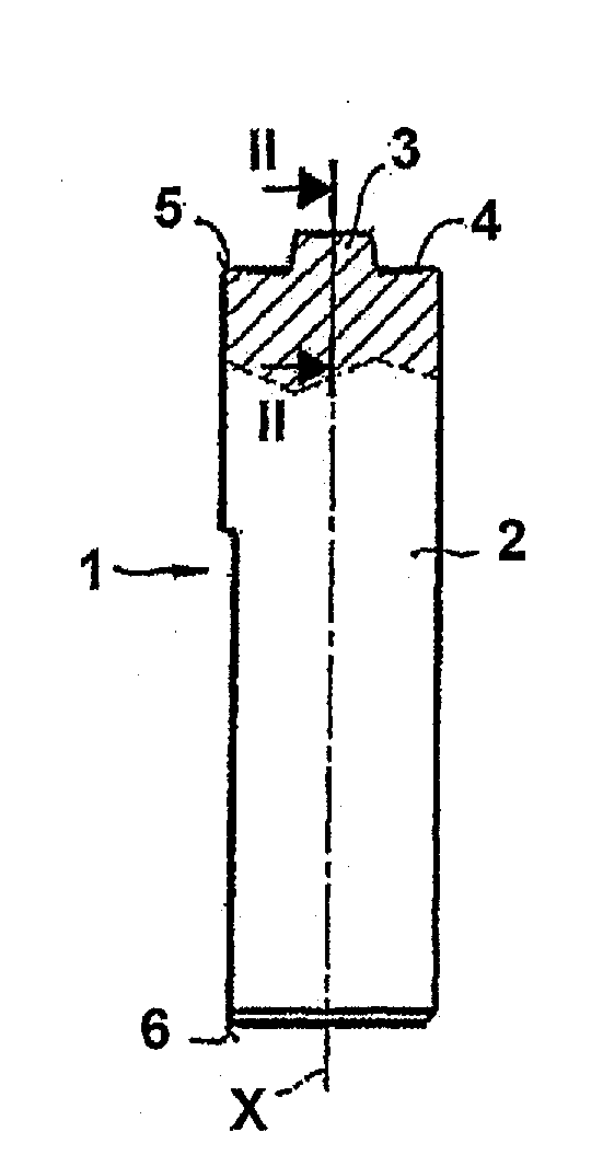
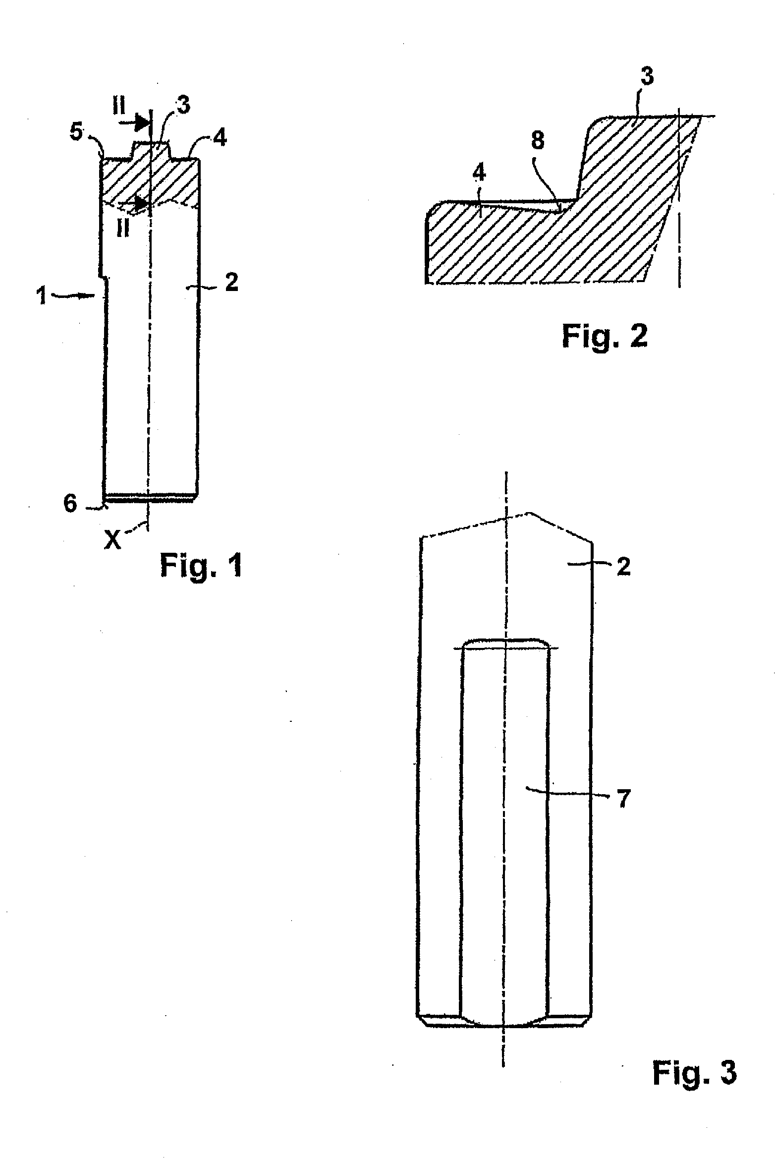
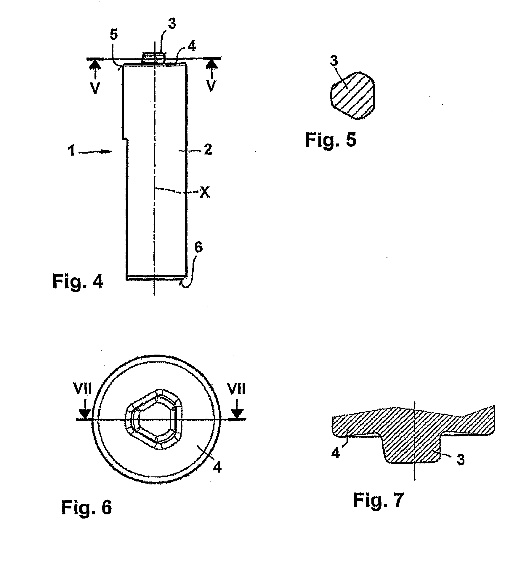
[0028]FIG. 1 through FIG. 3 as well as FIG. 4 through FIG. 7 show two friction stir welding tools 1, as they can be used within the scope of the invention. Each friction stir welding tool 1 has an approximately cylindrical shank 2 with two ends 5, 6. The first end 5 is respectively embodied with a shoulder region 4 running from the edge or a shoulder edge to the axis X of the shank 2 initially at an angle declining from up to 15°, which shoulder region then ascending merges respectively into a projecting pin 3 or pin arranged on the central axis X of the shank 2. The transition 8 from the shoulder region 4 to the pin 3 can thereby be embodied in a rounded manner, as can be seen from FIG. 2. Seen from the center of the shank 2 in the direction of the axis X, the pin 3 is embodied slightly tapering in a conical manner at an angle of approximately 5° to 15°, preferably 7° to 12°. Furthermore, a guide groove 7 can be provided on the shank 2 starting from the second end 6, in order to re...


PUM

PropertyMeasurementUnit
Lengthaaaaaaaaaa
Percent by massaaaaaaaaaa

Abstract

The invention relates to a friction stir welding tool (1) with an essentially cylindrical shank (2), which has a peg (3) with a smaller diameter projecting on one end (5) starting from a shoulder region (4) of the shank (2). According to the invention it is provided in order to create a friction stir welding tool (1) for welding steel, that the friction stir welding tool (1), at least in the region of the peg (3) and in the shoulder region (4), is made of a hard metal containing 80% by weight to 98% by weight tungsten carbide with an average grain size of more than 1 μm and up to 20% by weight cobalt as well as optionally a total of up to 18% by weight titanium carbide, tantalum carbide, niobium carbide and/or mixed carbides thereof and at least in one of the referenced regions has a coating of one or more layers.

Description

CROSS-REFERENCE TO RELATED APPLICATIONS[0001]The present application is a U.S. National Stage of International Patent Application No. PCT / AT2008 / 000395 filed Oct. 31, 2008, and claims priority under 35 U.S.C. §119 and 365 of Austrian Patent Application No. A 1862 / 2007 filed Nov. 16, 2007. Moreover, the disclosure of International Patent Application No. PCT / AT2008 / 000395 is expressly incorporated by reference herein in its entirety.BACKGROUND OF THE INVENTION[0002]1. Field of the Invention[0003]The invention relates to a friction stir welding tool with an essentially cylindrical shank, which has a pin with a smaller diameter projecting on one end starting from a shoulder region of the shank.[0004]2. Discussion of Background Information[0005]Friction stir welding is a welding process known for approximately two decades, in which a tool of the type mentioned at the outset is placed with the pin-side end against workpieces to be joined and is set in rotation. Through the rotation of the...

Claims


Application Information

Patent Timeline
IPC IPC(8): B23K20/12
CPCB23K20/125
Inventor KOLBECK, CHRISTIANPITONAK, REINHARDWEISSENBACHER, RONALD
Owner BOEHLERIT GMBH & CO KG
Why Eureka
Try Eureka