

Discharge lamp
a discharge lamp and dielectric barrier technology, applied in the direction of gas-filled discharge tubes, incadescent envelopes/vessels, solid cathodes, etc., can solve the problems of high gas pressure and especially high applied voltage, inability to raise temperature by heating, and unreliable insulator-covered electrodes. , to achieve the effect of intensive irradiation of the lamp
- Summary
- Abstract
- Description
- Claims
- Application Information
AI Technical Summary
Benefits of technology
Problems solved by technology
Method used
Image

Examples
embodiment 1
[0018]The first embodiment of this invention is the discharge lamp with foil electrodes embedded oppositely in parallel along the axis in both sidewalls of the discharge vessel.
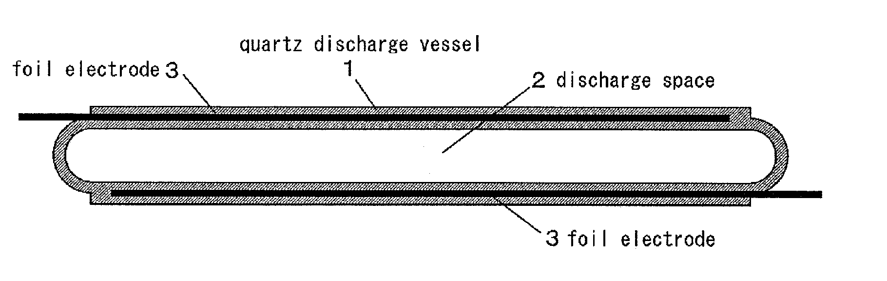
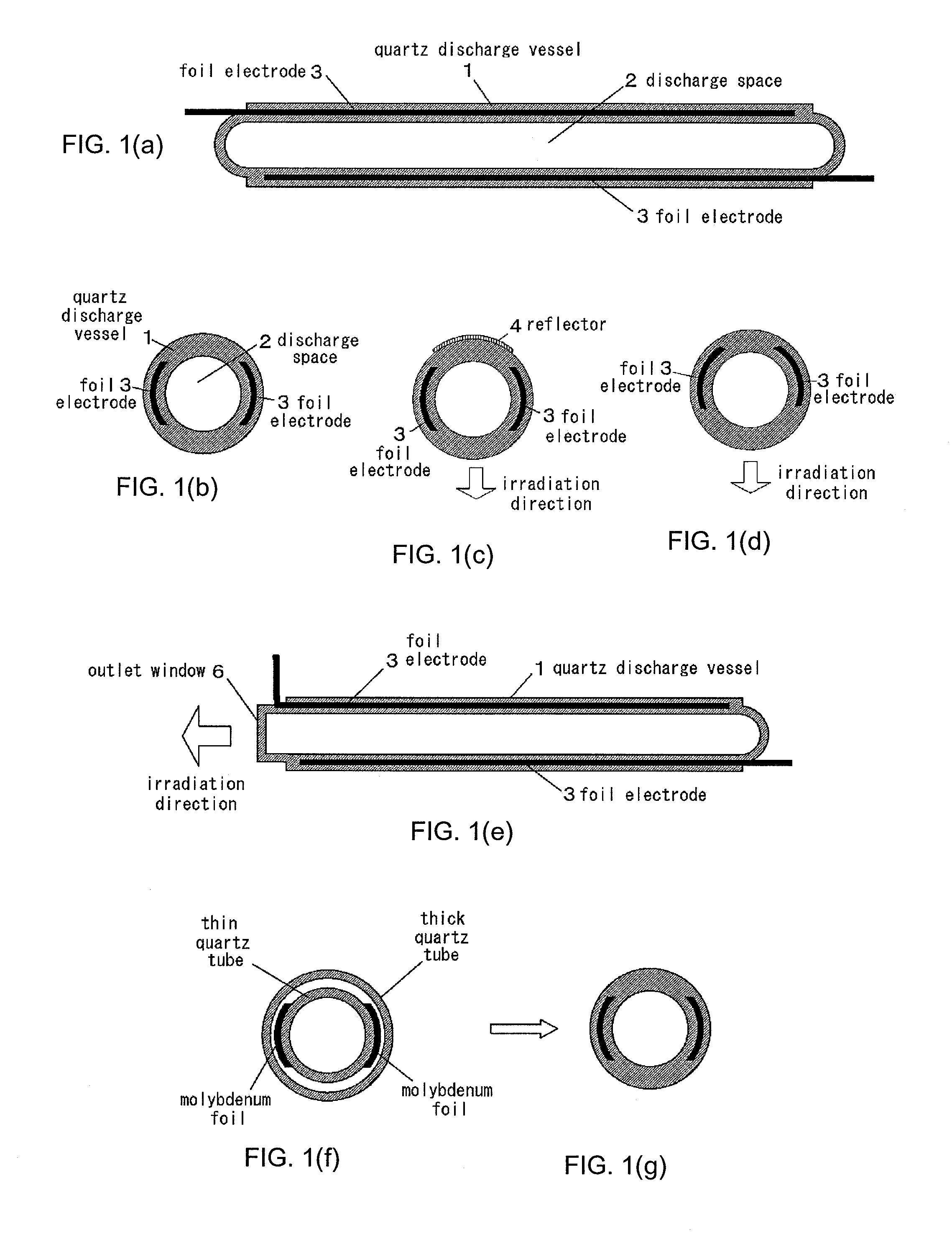
[0019]FIG. 1 shows the conceptual diagram of the discharge lamp of the first embodiment of this invention. FIG. 1(a) is the cross section along the axis of the discharge lamp. FIG. 1(b) is the cross section along the radius of the discharge lamp. FIG. 1(c) is the cross section along the radius of the discharge lamp with reflector. FIG. 1(d) is the cross section along the radius of the discharge lamp with electrodes of truncated V-shaped arc cross-section. FIG. 1(e) is the cross section along the axis of the discharge lamp with optical outlet window along the axis. FIGS. 1 (f) and (g) are the cross section along the radius to show the manufacturing process of the discharge lamp.
[0020]In FIG. 1, the quartz discharge vessel 1 is a single tube of quartz. It is also called simply a discharge vessel. It may be elli...
embodiment 2
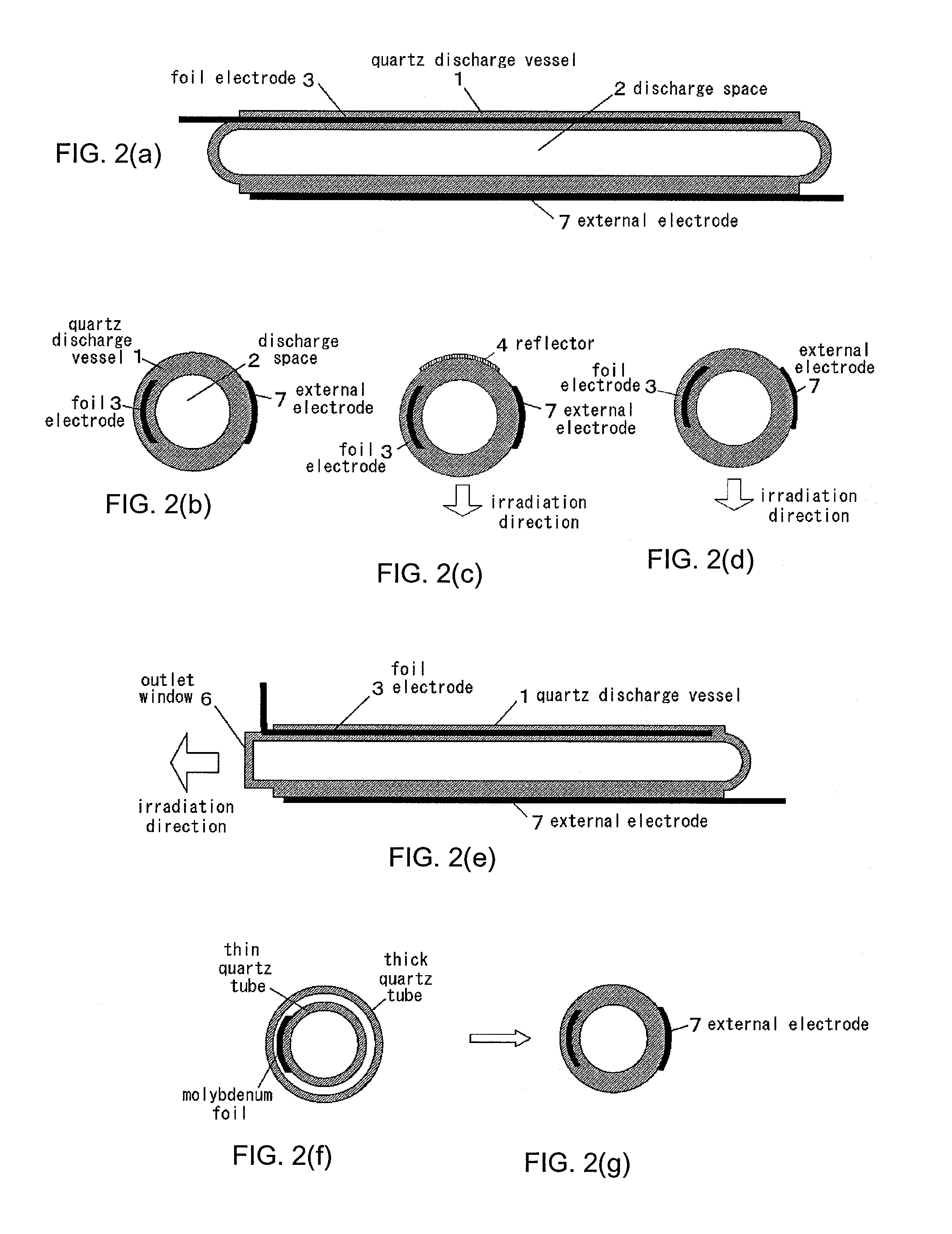
[0030]The second embodiment of this invention is the discharge lamp that a foil electrode is embedded along the axis in the wall of the discharge vessel and an external electrode is arranged along the axis on the outer cylindrical surface of the discharge vessel.
[0031]FIG. 2 is a conceptual diagram of the discharge lamp of the second embodiment of this invention. FIG. 2(a) is a cross section along the axis of the discharge lamp. FIG. 2(b) is a cross section along the radius of the discharge lamp. FIG. 2(c) is a cross section along the radius of the discharge lamp with a reflector. FIG. 2(d) is a cross section along the radius of the discharge lamp with the electrodes of truncated V-shaped cross section. FIG. 2(e) is a cross section along the radius of the discharge lamp with an optical outlet along the axis. FIGS. 2(f) and 2(g) are cross sections along the radius to show the manufacturing process of the discharge lamp. In FIG. 2, the external electrode 7 is an electrode arranged alo...
embodiment 3
[0036]The third embodiment of this invention is the discharge lamp that planar foil electrodes are embedded oppositely in parallel along the axis in both sidewalls of the discharge vessel.
[0037]FIG. 3 is a conceptual diagram of the discharge lamp of the third embodiment of this invention. FIG. 3(a) is a cross section along the axis of the discharge lamp. FIG. 3(b) is a cross section along the radius of the discharge lamp. FIG. 3(c) is a cross section along the radius of the discharge lamp with a reflector. FIG. 3(d) is a cross section along the radius of the discharge lamp with the electrodes of truncated V-shaped cross section. FIG. 3(e) is a cross section along the radius of the discharge lamp with an optical outlet window along the axis. Other basic constitutions are the same as the first embodiment. The explanation about the same part as the first embodiment is omitted.
[0038]The function and operation of the discharge lamp in the third embodiment of this invention constituted as...
PUM
 Abstract
Description
Claims
Application Information