Film deposition apparatus, film deposition method, and computer readable storage medium

a film deposition apparatus and film technology, applied in liquid surface applicators, chemical vapor deposition coatings, coatings, etc., can solve problems such as the inability to disclose a technology, the film may be filled with voids, etc., and achieve excellent gap-filling capability and high purity film

Active Publication Date: 2010-10-14
TOKYO ELECTRON LTD
View PDF76 Cites 56 Cited by
  • Summary
  • Abstract
  • Description
  • Claims
  • Application Information

AI Technical Summary

Benefits of technology

[0021]The present invention has been made in view of the above, and provides a film deposition apparatus and a film deposition method for depositing a film on a substrate by carrying out plural cycles of supplying in turn at least two source gases to the substrate in order to form plural layers of a reaction product, which can provide an excellent gap-filling capability and deposit a high purity film, and a storage medium storing a computer program for carrying out the film deposition method.

Problems solved by technology

However, a void may be caused in the film that fills the concave portion even by the ALD method, when the concave portion has a fairly large aspect ratio or a reverse-tapered shape.
Patent Documents 1 through 9 do not disclose a technology that can address such problems.

Method used


Image

  • Film deposition apparatus, film deposition method, and computer readable storage medium
  • Film deposition apparatus, film deposition method, and computer readable storage medium
  • Film deposition apparatus, film deposition method, and computer readable storage medium

Examples


first embodiment

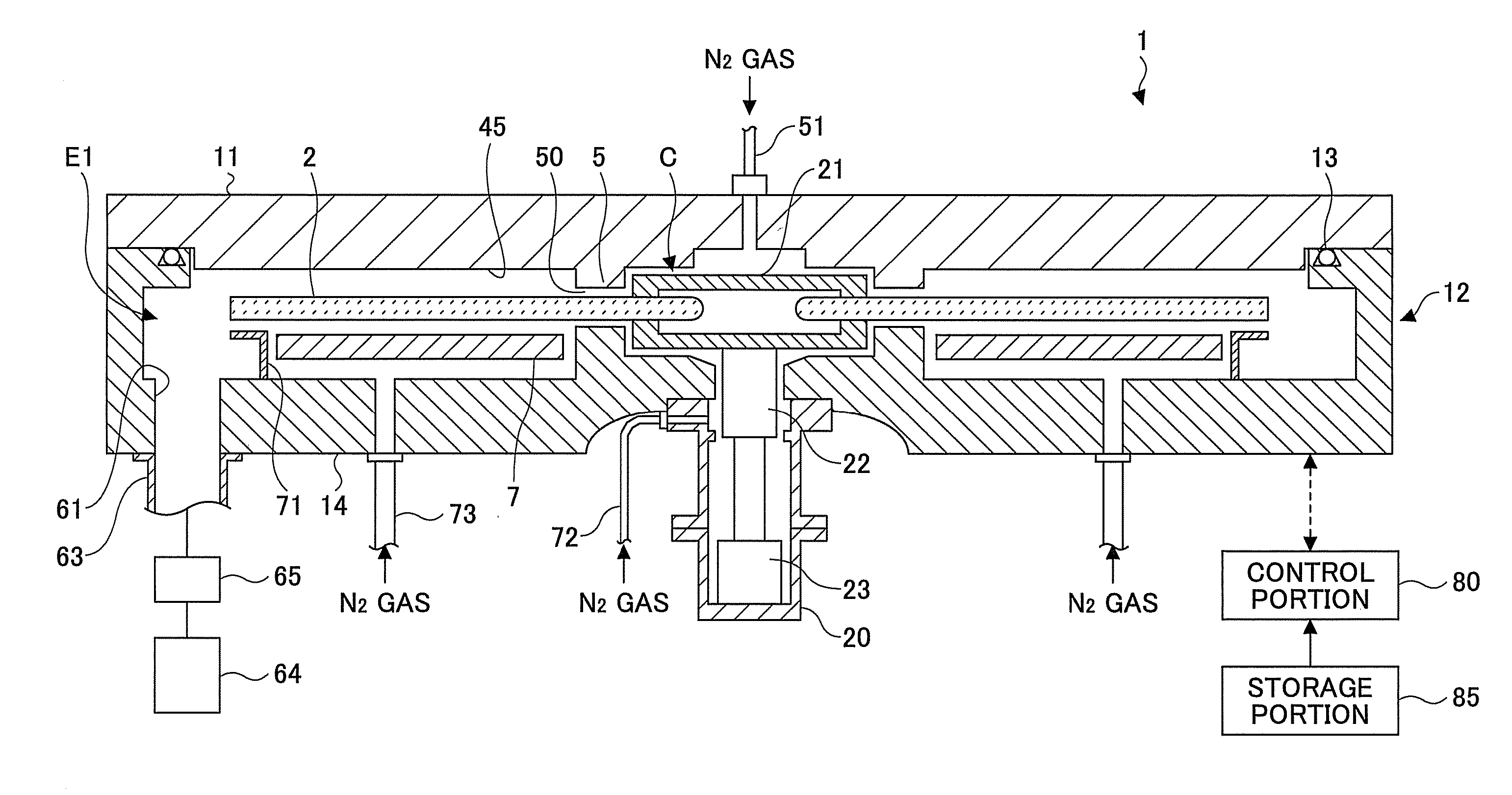
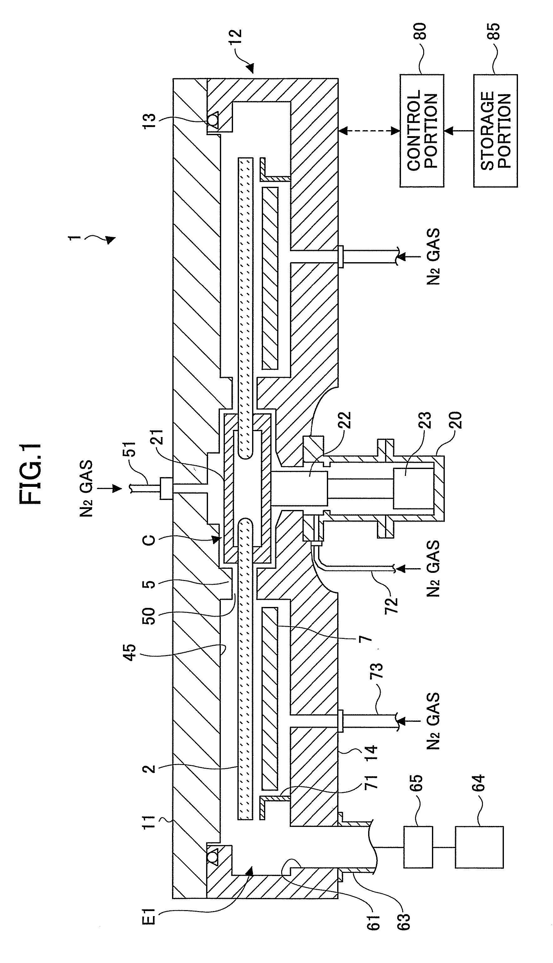
[0053]Referring to FIGS. 1 through 3, a film deposition apparatus according to a first embodiment of the present invention has a vacuum chamber 1 having a flattened cylinder top view shape, and a turntable 2 that is located inside the vacuum chamber 1 and has a rotation center in a center of the vacuum chamber 1. The vacuum chamber 1 has a chamber body 12 that has a substantial cup-shape and accommodates the turntable 2, and a ceiling plate 11 that has a circular plate shape and closes an upper opening of the chamber body 12. The ceiling plate 11 is hermetically attached on the chamber body 12 via a sealing member such as an O-ring 13, and can be moved upward / downward to be opened / closed by a driving mechanism (not shown).

[0054]The turntable 2 is rotatably attached at its center onto a cylindrically shaped core portion 21. The core portion 21 is fixed on a top end of a rotational shaft 22 that extends in a vertical direction. The rotational shaft 22 penetrates a bottom portion 14 of...

second embodiment

[0104]Next, a film deposition apparatus according to a second embodiment of the present invention is explained with reference to FIGS. 15 through 17. In the film deposition apparatus, a plasma injector 250 serving as a plasma generating portion is provided between the second reaction gas nozzle 32 and the heating lamp 210 along the rotation direction of the turntable 2, as shown in FIG. 15.

[0105]A plasma injector 250 includes an injector body 251 serving as a chassis. Referring to FIGS. 16 and 17, the injector body 251 is divided into two spaces having different widths by an isolation wall 252 extending along a longitudinal direction of the injector body 251. One of the two spaces is a gas activation chamber 253 serving as a gas activation passage where a gas for generating plasma is activated into plasma, and the other one of the spaces is a gas introduction chamber 254 serving as a gas introduction passage from which the gas for generating plasma is introduced into the gas activat...

third embodiment

[0113]Next, a film deposition apparatus according to a third embodiment of the present invention is explained with reference to FIG. 18. In this embodiment, at least one of boron (B) and phosphor (P) is doped as a dopant with the silicon oxide film 242 in order to facilitate reflow of the silicon oxide film 242. Specifically, the film deposition apparatus according to this embodiment can be realized by providing, for example, the film deposition apparatus according to the first embodiment with a third gas nozzle (third reaction gas supplying portion) 150 for supplying, for example, phosphine (PH3) gas as a phosphorous doping gas (third reaction gas). The third gas nozzle 150 may be made of, for example, quartz, and is arranged between the second reaction gas nozzle 32 and the heating lamp 210 in this embodiment.

[0114]The third gas nozzle 150 has substantially the same configuration as the gas nozzles 31, 32, 200, 41, 42 and is arranged to horizontally extend from the circumferential...


PUM

PropertyMeasurementUnit
diameteraaaaaaaaaa
heightaaaaaaaaaa
inner diameteraaaaaaaaaa

Abstract

A rotation table on which a wafer is placed is rotated around a vertical axis in order to supply to an upper surface of the wafer a first reaction gas for allowing the first reaction gas to be adsorbed on the upper surface, an auxiliary gas that reacts with the first reaction gas to produce an intermediate product having reflowability, and a second reaction gas that is reacted with the intermediate product to produce a reaction product in this order; and the reaction product is heated by a heating lamp in order to densify the reaction product.

Description

CROSS-REFERENCE TO RELATED APPLICATION[0001]This application claims the benefit of priority of Japanese Patent Application No. 2009-095210, filed on Apr. 9, 2009 with the Japanese Patent Office, the entire content of which is hereby incorporated by reference.BACKGROUND OF THE INVENTION[0002]1. Field of the Invention[0003]The present invention relates to a film deposition apparatus and a film deposition method for depositing a film on a substrate by carrying out plural cycles of supplying in turn at least two source gases to the substrate in order to form plural layers of a reaction product, and a storage medium storing a computer program for carrying out the film deposition method.[0004]2. Description of the Related Art[0005]Along with further reduction of pattern feature size in semiconductor devices, a better gap-filling capability in a gap-filling process where concave portions such as trenches formed in a semiconductor wafer are filled with the deposited film is being demanded. ...

Claims


Application Information

Patent Timeline
Patent Type & Authority Applications(United States)
IPC IPC(8): C23C16/52C23C16/00C23C16/46
CPCC23C16/402C23C16/45578C23C16/45551C23C16/54H01L21/67115H01L21/6719H01L21/67207H01L21/68764H01L21/68771C23C16/45519C23C16/482C23C16/463C23C16/46C23C16/458C23C16/45536
Inventor KATO, HITOSHIHONMA, MANABUKIKUCHI, HIROYUKI
Owner TOKYO ELECTRON LTD
Why Eureka
Try Eureka