Chain

a low friction, chain technology, applied in the direction of chain elements, belts/chains/gearrings, chain elements, etc., can solve the problems of large amount of abrasive wear of link plates, affecting the service life of chain components, so as to reduce the concentration of sliding contact at the same position on each link plate, the effect of reducing the amount of abrasive wear

Active Publication Date: 2010-10-21
TSUBAKIMOTO CHAIN CO
View PDF16 Cites 28 Cited by
  • Summary
  • Abstract
  • Description
  • Claims
  • Application Information

AI Technical Summary

Benefits of technology

[0011]In one preferred embodiment, the chain includes a plurality of asymmetric link plates having the above-described shape. These asymmetric link plates are connected in alternating relationship by connecting link plates. All of the edges of the connecting link plates are spaced from the guide member as the asymmetric link plates travel in sliding contact with the guide member. A large pivoting movement of the asymmetric link plates can be achieved so that sliding contact at the same position on each of the asymmetric link plates is reduced and abrasive wear is reduced. At the same time, disturbances are more effectively absorbed by pivoting movement of the asymmetric link plates, and more effective reduction of vibration and contact noise can be realized.
[0012]In another preferred embodiment, in each asymmetric link plate, the point on a line connecting the centers of the front and rear connecting holes from which the perpendicular distance to the guide member-contacting edge of the asymmetric link plate is maximum is located rearward, with reference to the direction of travel of the chain, of a location midway between the centers of the front and rear connecting holes thereof. In this embodiment, the direction of a turning moment of the link plate generated as a result of friction between the link plate and the guide surface is the same as the direction of the turning moment generated by pressure applied to the link plate by the guide. Thus increased pivotal movement of the link plate takes place, concentration of sliding contact at the same position on each link plate is reduced, and abrasive wear is reduced accordingly. At the same time, disturbances are absorbed by pivotal movement more effectively, and vibration and contact noise are reduced.
[0013]In still another embodiment, asymmetric link plates are arranged along the length of the chain in two sets in alternating relationship. The link plates of a first set have their widest parts forward of the midpoint between their front and rear connecting holes with reference to a direction of chain travel, and the link plates of a second set having their widest parts rearward of the midpoint between their front and rear connecting holes with reference to the direction of chain travel. In this embodiment, whatever the direction of travel of the chain is, sliding contact resistance can be reduced, and disturbances can be absorbed so that vibration and contact noise are reduced.
[0014]In still another preferred embodiment, a portion of the continuously curved edge of the asymmetric link plate that contacts the guide is in the shape of an arc centered on a point on an extension of the line perpendicularly intersecting the point on a line connecting the centers of the front and rear connecting holes from which the distance to the edge of the link plate is a maximum. In this case, the shape of the wedge-shaped space in front of the sliding contact area is not changed as a result of pivoting movement of the link plate. Thus, sliding contact resistance is reduced stably, and the effect of disturbances is reduced, whereby vibration and contact noise can be reduced.
[0015]In an embodiment in which the link plates of the chain are plates of a chain from the group consisting of roller chains and rollerless bushing chains, and in which least one of the link plates has a second edge opposite from the continuously curved edge, the second edge is also a continuously curved edge, and the distance measured perpendicularly from a point on a line connecting the centers of the front and rear connecting holes to the second edge is also a maximum when the last-mentioned point is spaced from a location midway between the centers of the front and rear connecting holes, either edge can come into sliding contact with a guide surface. The sliding contact area is reduced, and dynamic pressure in the lubricant reduces sliding contact resistance. Here again, the position on the plate at which sliding contact occurs varies, and abrasion wear is reduced. Disturbances are also absorbed by pivotal movement of the link plate, whereby vibration and contact noise are reduced.
[0016]Many of the advantages of the invention can be realized in a silent chain in which link plates are toothed link plates, and in which the convex edge of is a back of a toothed link plate. That is, the sliding contact area is reduced, dynamic pressure is generated in the lubricant to reduce sliding contact resistance, and the location on the link plate back at which sliding contact takes place varies, reducing abrasion wear. In addition, pivotal movement of the plates reduces vibration and contact noise.

Problems solved by technology

These contact locations are unaffected by changes in chain tension, and a large amount of abrasive wear of the link plates occurs.
Consequently, intrusion of powder, dust and the like produced by wear occurs, and vibration, contact noise and the like are liable to occur.

Method used


Image

  • Chain
  • Chain
  • Chain

Examples


first embodiment

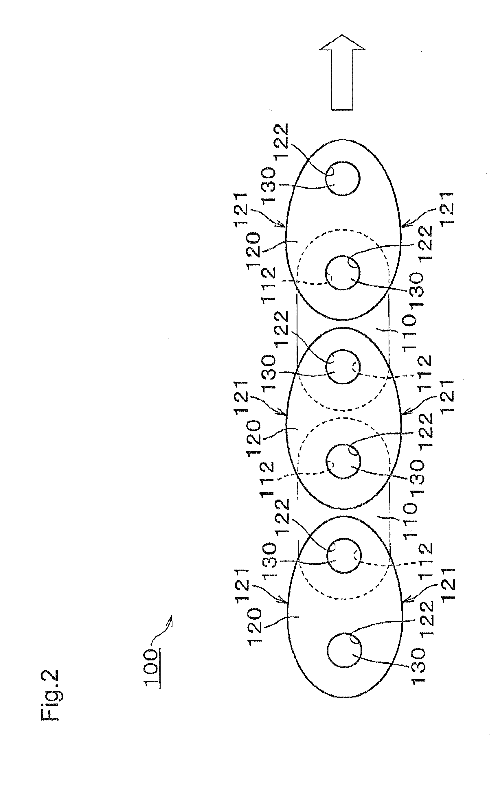
[0032]The chain 100, according to the invention, is formed as shown in FIG. 2. On each side of the chain, a plurality of inner link plates 110 and a plurality of outer link plates 120 are arranged in alternating, overlapping relationship, and interconnected articulably to one another by connecting pins 130 in connecting holes 112 and 122.

[0033]In this embodiment, which is a rollerless bushing chain, bushings are fitted to connecting holes 112 of the inner link plates 110, and connecting pins 130 extend through and fit loosely in the bushings as in the above-described chain 500 of FIG. 10. In the case of a roller chain, the chain structure is similar to that of FIG. 2, except that rollers are loosely rotatable on the outer circumferences of the bushings.

[0034]The upper and lower edges of the outer link plate 120 are convexly shaped edges 121, formed in a continuously curved shape. The distance between the upper and lower edges of the inner link plates 110 is to be smaller than the di...

second embodiment

[0042]In the invention shown in FIG. 8, a chain 200 is composed of alternating inner and outer links comprising respectively inner link plates 210 and outer link plates 220. The links are arranged in alternating, overlapping relationship along the length of the chain and interconnected articulably by connecting pins 230. Inner links are formed of two inner plates connected in laterally spaced relationship by a pair of bushings fitted to bushing holes in the link plates. The outer links are formed by a pair of laterally spaced outer link plates connected by pins fitted to pin holes in the outer plates and extending rotatably through bushings of the inner links whereby the inner and outer links are connected in articulating relationship. In the case of a roller chain, rollers can be loosely fitted on outer circumferences of the bushings.

[0043]The upper and lower edges 221 of the outer link plates 220 and the upper and lower edges 211 of the inner link plates 210 are convex and formed ...

third embodiment

[0045]In the invention shown in FIG. 9, a chain 300 is composed of toothed inner link plates 310 and toothed outer link plates 320 arranged in widthwise rows interleaved with one another and connected articulably by connecting pins as in a conventional silent chain.

[0046]The lower edges of the link plates 310 and 320 are respectively formed with teeth 313 and 323 for meshing engagement with sprockets (not shown).

[0047]The upper edges 321 of the outer link plates are in the form of continuous convex curves for sliding contact with a guide member. As in the outer link plate 120 of the first embodiment, shown in FIG. 3, the distance between a line connecting the centers of the front and rear connecting holes 322 of these outer link plates and the convexly-shaped edge 321 is a maximum at a position spaced from the midpoint between the connecting holes. The parts of the link plate backs that contact the guide surface are also preferably in the form of an arc as in the previously describe...


PUM


Abstract

In a transmission chain having link plates with convex edges for sliding contact with a guide surface, the plates are asymmetric in shape so that the distance from a line connecting the centers of the connecting holes and the convex edge is greatest at a position other than at the midpoint between the connecting holes. A pivoting action of the link plates takes place as they slide over a guide surface, changing the abutment point.

Description

CROSS-REFERENCE TO RELATED APPLICATION[0001]This application claims priority on the basis of Japanese patent application 2009-099675, filed Apr. 16, 2009. The disclosure of Japanese application 2009-099675 is hereby incorporated by reference.FIELD OF THE INVENTION[0002]This invention relates to a low friction chain for use in a power transmission mechanism, a conveying machine, or the like. The invention relates more specifically to a low friction chain particularly suitable for use as a timing chain in an automobile engine.BACKGROUND OF THE INVENTION[0003]In many power transmission mechanisms using a chain drive, an endless chain is in meshing engagement with a driving sprocket and with one or more driven sprockets. For example, in the timing drive of an automobile engine, a chain is driven by a crankshaft sprocket and drives one or more a camshaft sprockets. The chain is typically in sliding contact with one or more guide members including a movable tensioner lever and a fixed gui...

Claims


Application Information

Patent Timeline
Patent Type & Authority Applications(United States)
IPC IPC(8): F16G13/06F16H7/18F16H7/06
CPCF16G13/02F16G13/06F16G13/04
Inventor MIYAZAWA, TOSHIHIKOSAITOH, TOYONAGA
Owner TSUBAKIMOTO CHAIN CO
Why Eureka
Try Eureka