Intake manifolds for internal combustion engine

a technology for internal combustion engines and intake manifolds, which is applied in the direction of machines/engines, combustion air/fuel air treatment, and feed systems, etc. it can solve the problems of reducing the efficiency of the engine, the plenum is not sufficiently sized to create resonance chambers or vacuum cavities, and the synthetic distribution chamber further does not provide a large volume vacuum chamber. , to achieve the effect of improving performan

Inactive Publication Date: 2010-10-28
JASPER GENE
View PDF24 Cites 5 Cited by
  • Summary
  • Abstract
  • Description
  • Claims
  • Application Information

AI Technical Summary

Benefits of technology

[0009]It is an object of the intake manifold for an internal combustion engine to have multiple tuned resonance chambers. This provides a pair of pressure equalization tanks with sufficient volume so the volume of air that is being supplied to each cylinder is essentially the same thereby providing improved performance. The shape of the tanks provides optimal volume while they are configured to fit around existing engine components.
[0010]It is an object of the intake manifold for an internal combustion engine to use cylinder feeder tubes that have flared ends. The flared ends reduce turbulent air flow into each tube and provide a funnel for the air to enter into each tube.
[0011]It is an object of the intake manifold for an internal combustion engine for the plenum chamber to be constructed from an assembly of parts as opposed to being cast. The assembly allows for custom tuning and placement of the various components wherein casting provides for a fairly fixed arrangement of components, sizes and shapes.
[0013]It is another object of the intake manifold for an internal combustion engine for each of the separate ducting tubes to have lengths that are specifically designed to provide optimal air flow and volume. The optimal design provides at least the volume that will be drawn into a cylinder with each stroke. This ensures that sufficient volume is in close proximity to the cylinder intake valve.
[0014]It is still another object of the intake manifold for an internal combustion engine for the ends of the ducting tubes to be tipped or oriented into the resonance chamber this reduces air flow direction changes thereby providing a more linear flow from the intake port of the plenum through the ducting ports.
[0015]It is still another object of the intake manifold for an internal combustion engine for the diameter of the ducting tubes to provide maximum air flow to minimize flow restriction through the tubes. The tubes many further have different or tapered diameters to provide consistent air flow into each cylinder to provide consistent power from all cylinders.

Problems solved by technology

Obstructions and poor design of the manifold can cause turbulent air within the manifold and thereby decrease the efficiency of the engine.
While this patent provides a number of intake pipes that all terminate within the plenum the design uses a single plenum and the plenum is not sufficiently sized to create a resonance chamber or a vacuum cavity that has sufficient volume to provide even pressure for all of the intake tubes.
The synthetic distribution chamber further does not provide a large volume vacuum chamber to provide equal air flow to all of the cylinders.
This patent does not address a case where multiple chambers are needed wherein the pressure in each chamber should be essentially the same to allow the pistons to operate at a higher output level.

Method used


Image

  • Intake manifolds for internal combustion engine
  • Intake manifolds for internal combustion engine
  • Intake manifolds for internal combustion engine

Examples


Embodiment Construction

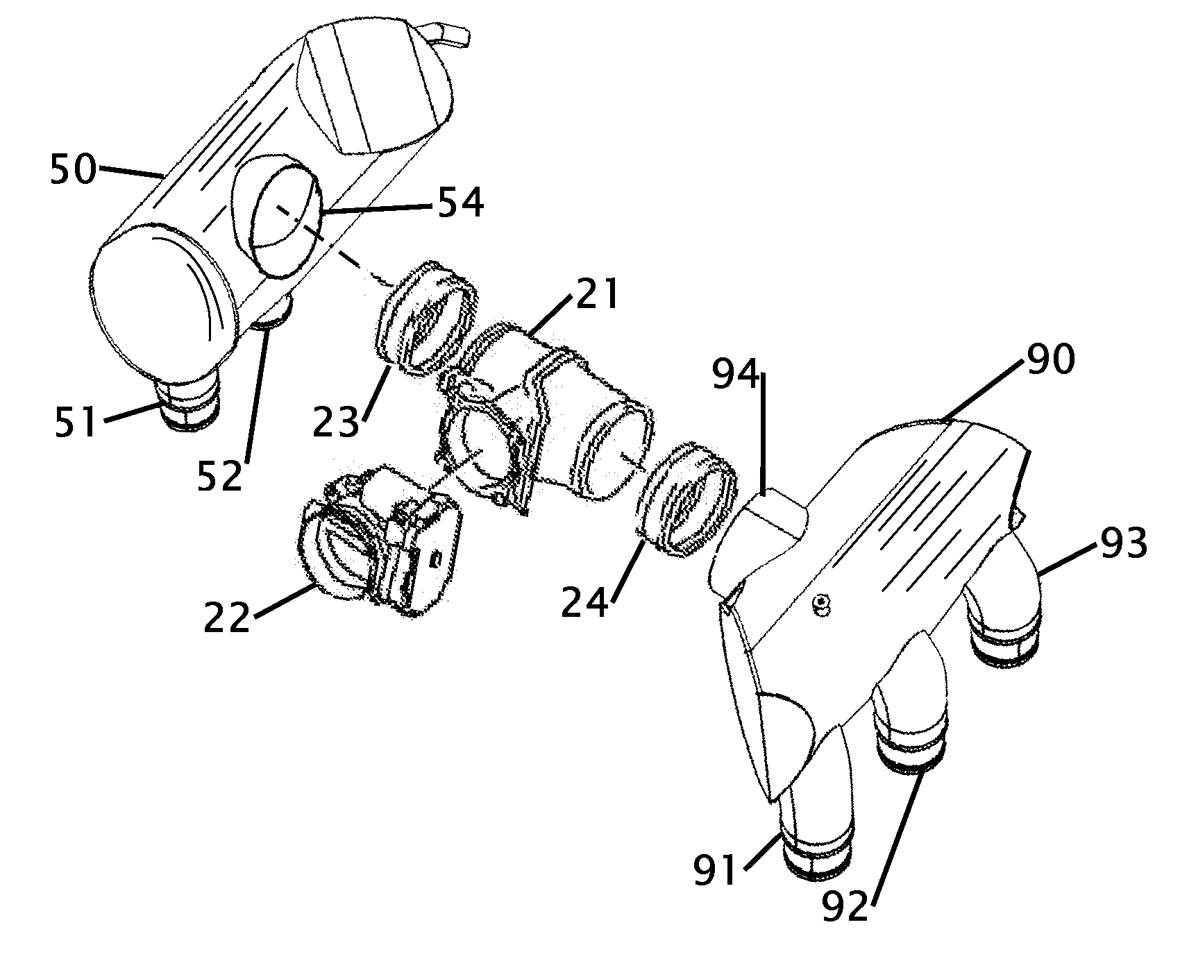
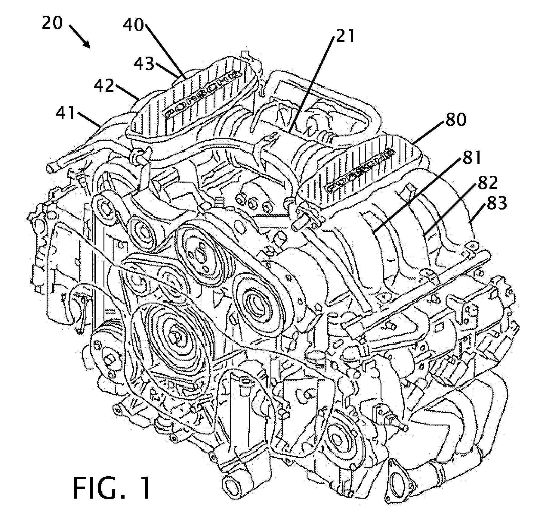
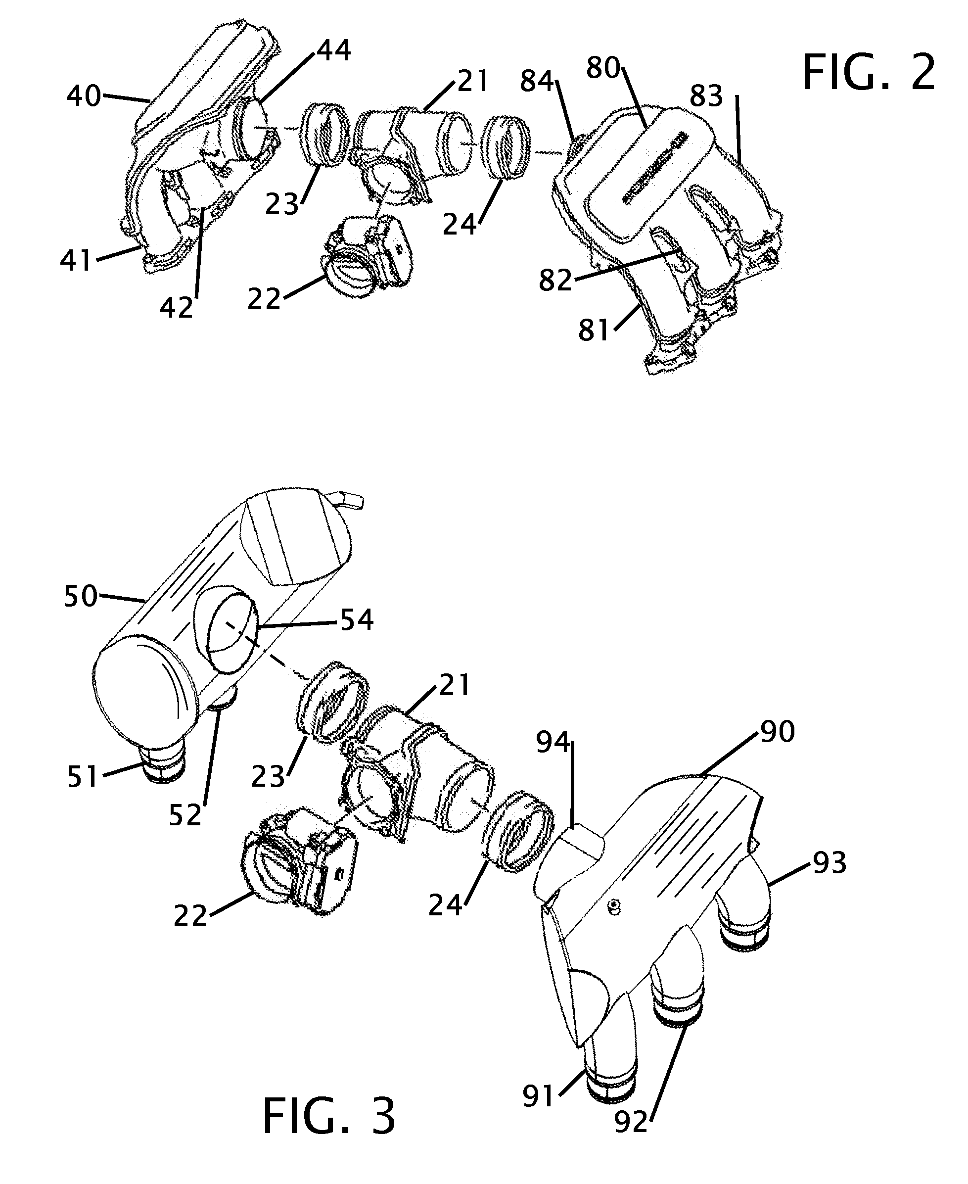
[0026]FIG. 1 shows a perspective view of a prior art motor with prior art plenums. This figure shows a typical configuration of an engine 20 with the plenum components. This figure is a stock Porsche engine 20. The air is brought into the engine from an air filter (not shown) where it is regulated through a throttle body (shown in FIG. 2). The throttle body is connected to a plenum T 21. The plenum T 21 diverts air from a single throttle body into two separate directions where the air flow then enters into a left plenum 40 and a right plenum 80. These prior art plenums have minimal internal volume and just split the air from a single input port to three intake conduits that are shown as items 41, 42 and 43 for the left stock plenum 40, and as items 81, 82 and 83 for the right stock plenum. The stock plenums are fabricated with a casting process. The stock air flow components are shown removed from the engine in FIG. 2 where they are more easily compared to the improved plenum design...


PUM


Abstract

Improvements in an intake manifold for an internal combustion engine having separate plenum intake storage tanks. Each plenum stores an internal large volume of air that more easily drawn into intake conduits that feed air into the intake ports of an engine. Each plenum has one or more intake ports where air is supplied from a throttle body and a plurality of intake conduits. In the preferred embodiment there are three intake conduits that provide air for a total of six cylinders. The plenums are constructed from formed pieces to provide thinner walls thereby increasing the internal volume of the plenums. The plenums further have connection ports for sensors. The intake conduits terminate a distance within the plenum and have flared ends that can be oriented towards the center of the plenum to improve air movement and flow from the input.

Description

BACKGROUND OF THE INVENTION[0001]1. Field of the Invention[0002]This invention relates to improvements in an air intake manifold. More particularly the intake manifold is directed to an automobile air intake manifold that is configured to improve air flow into an automobile engine.[0003]2. Description of Related Art including information disclosed under 37 CFR 1.97 and 1.98[0004]An air intake manifold exists between the air filter and the head of an engine. This area is under a vacuum while the engine is in operation. The vacuum is caused by the pistons drawing in air. In general the faster the engine turns the greater amount of air passes through the intake manifold. The design and structure of the intake manifold has a significant effect on the performance of an engine. If the manifold has a restriction the volume of air is decreased. Obstructions and poor design of the manifold can cause turbulent air within the manifold and thereby decrease the efficiency of the engine. Several ...

Claims


Application Information

Patent Timeline
Patent Type & Authority Applications(United States)
IPC IPC(8): F02M35/10
CPCF02M35/10039F02M35/116F02M35/10045
Inventor JASPER, GENE
Owner JASPER GENE
Why Eureka
Try Eureka