LIDAR system utilizing SOI-based opto-electronic components

Active Publication Date: 2010-10-28
CISCO TECH INC
View PDF22 Cites 94 Cited by
  • Summary
  • Abstract
  • Description
  • Claims
  • Application Information

AI Technical Summary

Benefits of technology

[0007]The need remaining in the art is addressed by the present invention, which relates to a “LIght Detection And Ranging” (LIDAR) system and, more particularly, to a

Problems solved by technology

The amount of energy that is emitted from these lasers is typically limited by the laser safety regulations of the country where the LIDAR units are sold, impacting the maximum range over which these devices may be used.
This phased array system is gene

Method used


Image

  • LIDAR system utilizing SOI-based opto-electronic components
  • LIDAR system utilizing SOI-based opto-electronic components
  • LIDAR system utilizing SOI-based opto-electronic components

Examples


Embodiment Construction

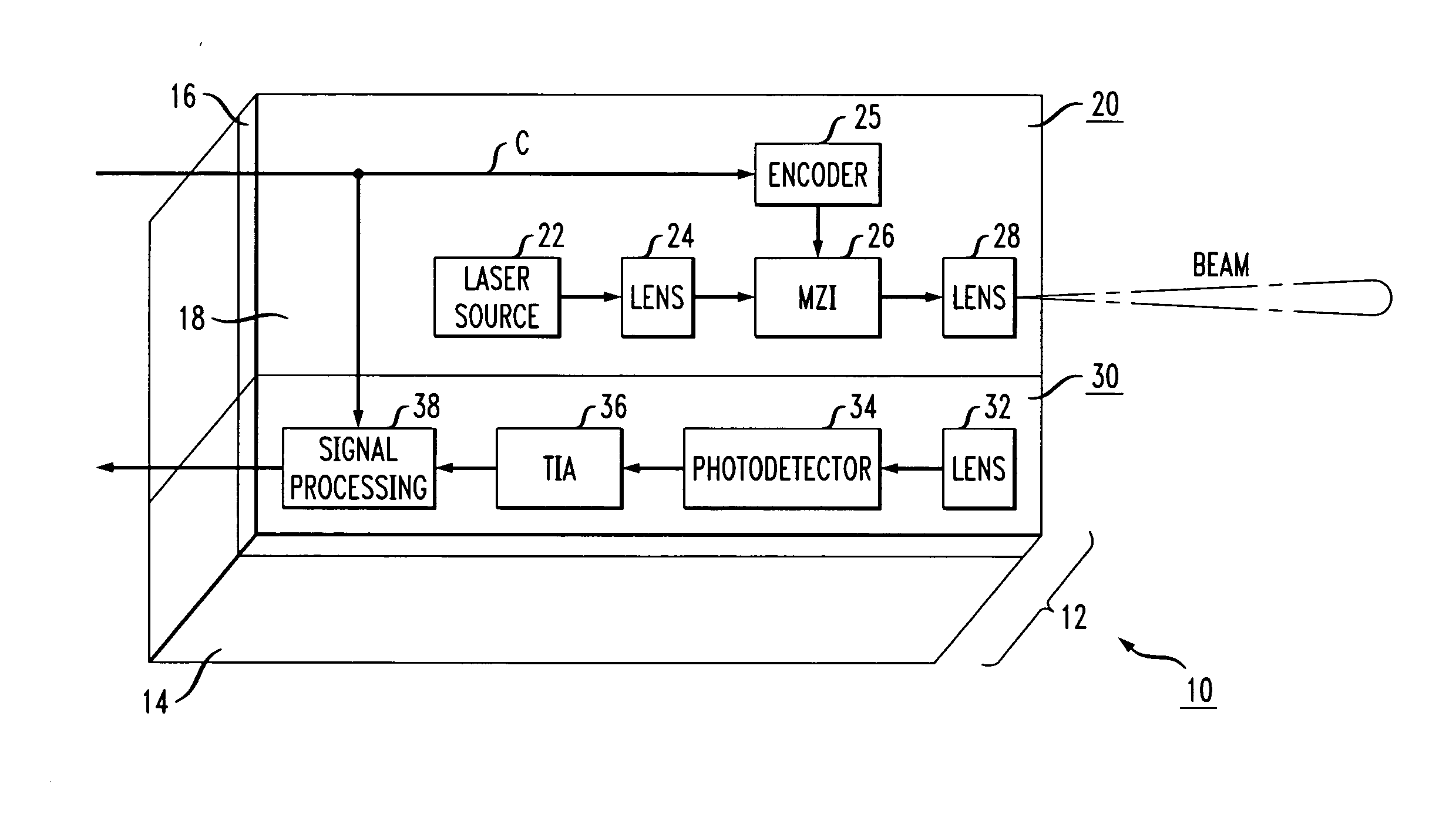
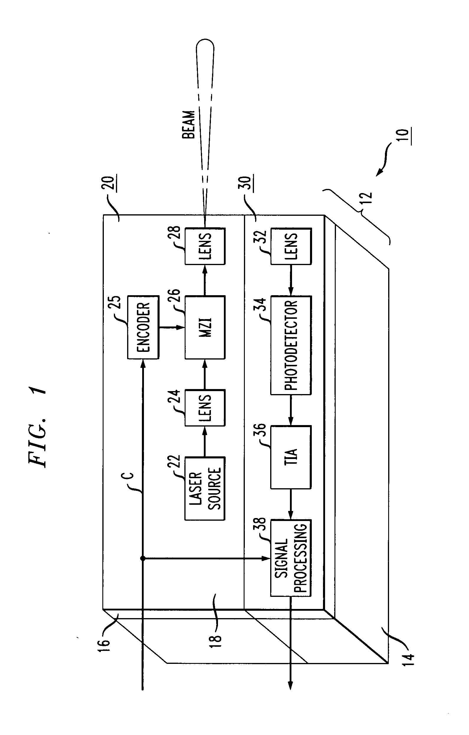
[0025]FIG. 1 illustrates, in an isometric view, an exemplary LIDAR system 10 integrated within an SOI-based platform in accordance with the present invention. In this particular embodiment, the various components of LIDAR system 10 are integrated within a single SOI structure 12. As will be discussed in other examples below, a “multi” module arrangement may also be utilized. Referring to FIG. 1 in particular, however, SOI structure 12 is illustrated as comprising a silicon substrate 14, an overlying insulating layer 16 (formed of a dielectric material, such as silicon dioxide and often referred to as the “buried oxide” layer), and a surface silicon layer 18 (hereinafter referred to as the “SOI layer”), where SOI layer 18 is generally of a sub-micron thickness.

[0026]LIDAR system 10 includes a LIDAR transmitter 20 and a LIDAR receiver 30, as shown in FIG. 1. LIDAR transmitter 20 includes a laser source 22, a focusing lens 24, an optical modulator 26 (such as, for example, a Mach-Zehnd...


PUM


Abstract

A compact, integrated LIDAR system utilizes SOI-based opto-electronic components to provide for lower cost and higher reliability as compared to current LIDAR systems. Preferably, an SOI-based LIDAR transmitter and an SOI-based LIDAR receiver (both optical components and electrical components) are integrated within a single module. The various optical and electrical components are formed utilizing portions of the SOI layer and applying well-known CMOS fabrication processes (e.g., patterning, etching, doping), including the formation of additional layer(s) over the SOI layer to provide the required devices. A laser source itself is attached to the SOI arrangement and coupled through an integrated modulation device (such as a Mach-Zehnder interferometer, i.e., MZI) to provide the scanning laser output signal (the scan controlled by, for example, an electrical (encoder) input to the input to the MZI). The return, reflected optical signal is received by a photodetector integrated within the SOI arrangement, where it is thereafter converted into an electrical signal and subjected to various types of signal processing to perform the desired type(s) of signal characterization/signature analysis.

Description

CROSS-REFERENCE TO RELATED APPLICATION[0001]This application claims the benefit of U.S. Provisional Application Ser. No. 60 / 762,994, filed Jan. 27, 2006.TECHNICAL FIELD[0002]The present invention is related to a “LIght Detection And Ranging” (LIDAR) system and, more particularly, to a compact, integrated LIDAR system utilizing SOI-based opto-electronic components to provide for lower cost and higher reliability as compared to current LIDAR systems.BACKGROUND OF THE INVENTION[0003]LIDAR systems are known to be utilized in a number of different arrangements including, but not limited to, “radar guns” as used by police to monitor traffic speeds, ground-based surveying, underwater scanning, airborne geo-mapping arrangements, aerosol monitoring, and the like. LIDAR systems may operate on the basis of various types of optical output signals, including continuous wave (CW) Doppler, pulsed Doppler, CW phase-shift keying (CW-PSK), pulsed PSK, and the like. In one exemplary arrangement, the L...

Claims


Application Information

Patent Timeline
IPC IPC(8): G01C3/08
CPCG01S7/4811G01S7/491G01S17/87G02B2006/12061G02B6/12004G02B6/122G01S17/936G01S17/931H01L2224/16225G01C3/08G01C3/00
Inventor ALBUQUERQUE, VIJAYPLEDE, DAVID
Owner CISCO TECH INC
Why Eureka
Try Eureka