Terahertz Frequency Domain Spectrometer with Integrated Dual Laser Module

a laser module and frequency domain technology, applied in the field of terahertz frequency domain spectrometers, can solve the problems of inability to interrogate discrete frequencies of interest, impose limitations on frequency resolution and the ability to look at specific frequency windows, and need to scan the delay line slowly

Inactive Publication Date: 2010-11-04
DEMERS JOSEPH R
View PDF17 Cites 33 Cited by
  • Summary
  • Abstract
  • Description
  • Claims
  • Application Information

AI Technical Summary

Benefits of technology

[0016]It is another object of the present invention to provide a terahertz spectrometer for the identification of a target spectrum with high resolution at low cost.
[0019]It is another object of the present invention to provide a method for adjusting the frequency of each laser in a terahertz spectrometer to provide higher frequency specificity and resolution.
[0021]It is still another object of the present invention to provide a field portable terahertz system in a highly compact configuration capable of identifying or imaging an object utilizing two lasers.

Problems solved by technology

However, the Fourier transform from the time domain into the frequency domain imposes limitations on the frequency resolution and upon the ability to look at specific frequency windows.
The largest drawback of prior art designs is the need to scan the delay line slowly and over a distance of the desired wavelength resolution (e.g., a 1 GHz resolution would require a 7.5 cm scan of the movable optical delay line) and the inability to interrogate discrete frequencies of interest.
The high degree of positional tolerance required to maintained on the movable optical delay assembly limit the utility of this approach in applications where compact size and operation in uncontrolled environments are required with wide temperature excursions and / or shock and vibration.

Method used


Image

  • Terahertz Frequency Domain Spectrometer with Integrated Dual Laser Module
  • Terahertz Frequency Domain Spectrometer with Integrated Dual Laser Module
  • Terahertz Frequency Domain Spectrometer with Integrated Dual Laser Module

Examples


Embodiment Construction

[0037]Details of the present invention will now be described, including exemplary aspects and embodiments thereof. Referring to the drawings and the following description, like reference numbers are used to identify like or functionally similar elements, and are intended to illustrate major features of exemplary embodiments in a highly simplified diagrammatic manner. Moreover, the drawings are not intended to depict every feature of actual embodiments or the relative dimensions of the depicted elements, and are not drawn to scale.

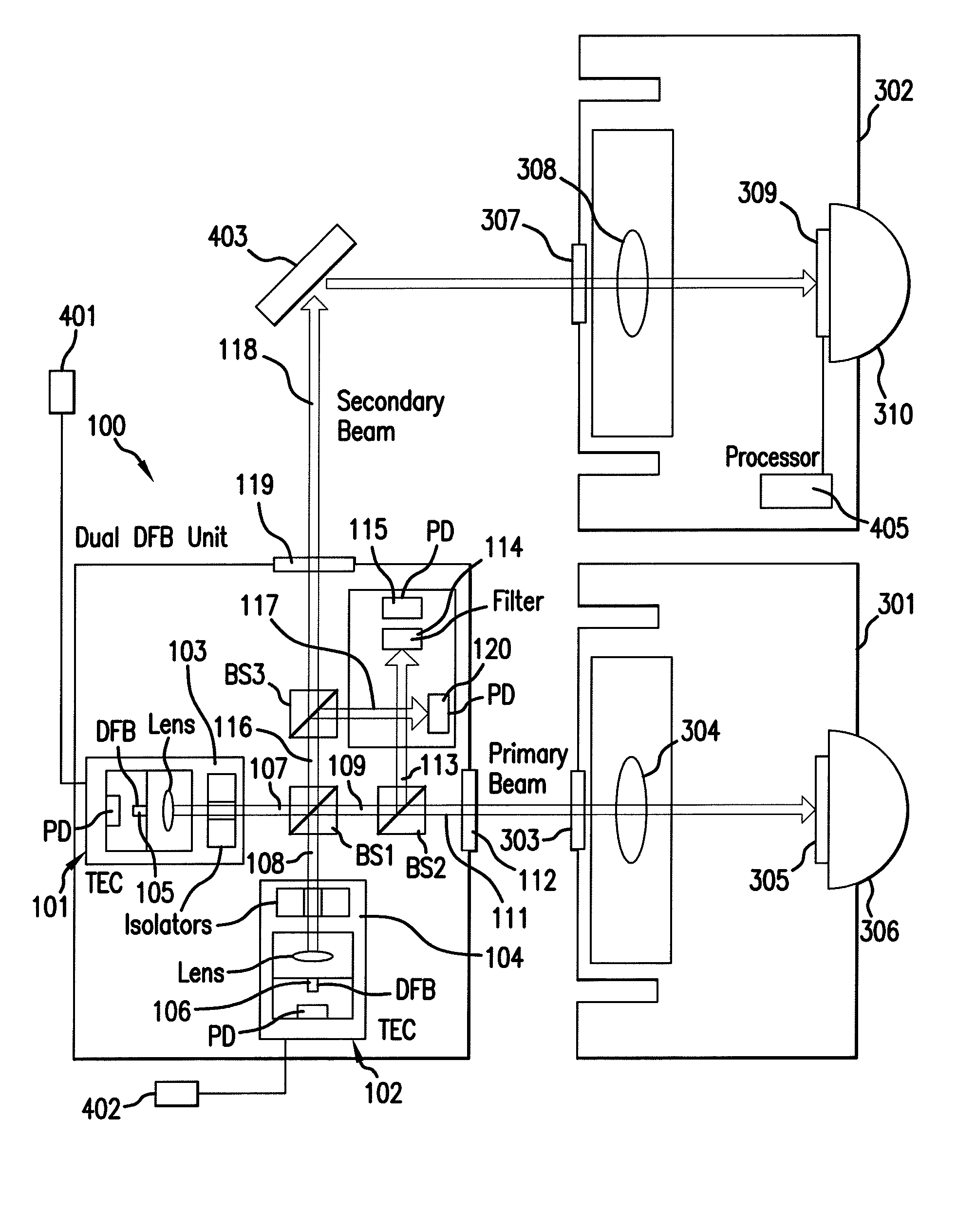
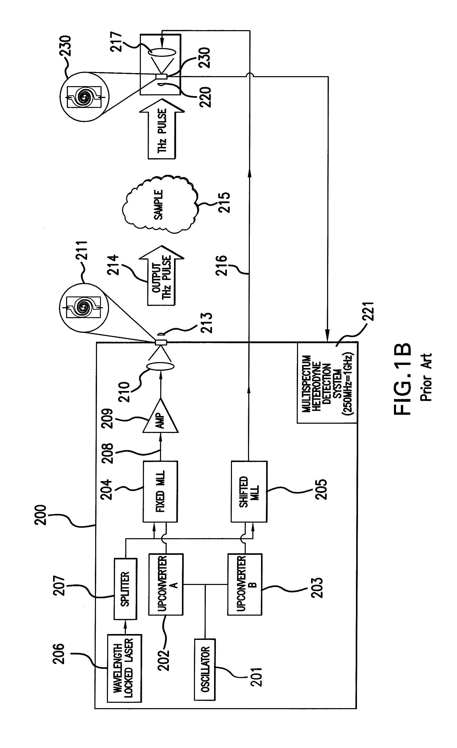
[0038]In the frequency-domain technique, CW THz radiation is produced through photomixing of the combined output of two single-frequency diode lasers in an ErGa:GaAs PCS. The wavelength of one (or both) of the lasers is tuned to vary the THz output frequency. In most spectroscopic applications of photomixing to date, the THz output beam from the PCS has been coupled to a sensitive broadband thermal detector (e.g., a liquid He bolometer or Golay cell), makin...


PUM


Abstract

An apparatus for analyzing, identifying or imaging an target including an integrated dual laser module coupled to a pair of photoconductive switches to produce cw signals in the range of frequencies from 100 GHz to over 2 THz focused on and transmitted through or reflected from the target; and a detector for acquiring spectral information from signals received from the target and using a multi-spectral homodyne process to generate an electrical signal representative of some characteristics of the target with resolution less than 250 MHz. The photoconductive switches are activated by laser beams from the dual laser module. The lasers in the module are tuned to different frequencies and have two distinct low frequency identification tones respectively that are used in conjunction with a stable optical filter element to permit precise determination of the offset frequency of the lasers.

Description

REFERENCE TO RELATED APPLICATIONS[0001]This application is related to U.S. patent application Ser. No. 11 / 796,069, filed Apr. 5, 2007 which is a continuation-in-part of U.S. patent application Ser. No. 11 / 669,685 filed Jan. 31, 2007.BACKGROUND OF THE INVENTION[0002]1. Field of the Invention[0003]The invention relates to microwave, millimeter wave and submillimeter wave spectroscopy systems and component and in particular to an integrated dual laser module for use in a homodyne transceiver useful for terahertz spectroscopy.[0004]2. Description of the Related Art[0005]Terahertz devices and systems generally refer to creating and detecting electromagnetic energy between 300 GHz and 3 terahertz (3 THz), or wavelengths from 100 to 1000 microns (0.1 to 1.0 millimeters), and also referred to as the submillimeter or far-infrared region of the electromagnetic spectrum. Terahertz energy can be created, for example, using short-pulsed lasers, heterodyne lasers, electronic diode multipliers, fr...

Claims


Application Information

Patent Timeline
Patent Type & Authority Applications(United States)
IPC IPC(8): G01J3/28H01S3/08H01S3/04H01S3/10
CPCG01J3/10G01N21/3581G01J3/42
Inventor LOGAN, JR., RONALD T.DEMERS, JOSEPH R.KASPER, BRYON L.
Owner DEMERS JOSEPH R
Why Eureka
Try Eureka