Over-wire rotation tool

a technology of over-wire and rotation tool, which is applied in the field of valve repair, can solve the problems of reducing cardiac output, reducing total stroke volume, and ultimate weakening of the left ventricle, and achieve the effect of facilitating such adjusting or removing

Active Publication Date: 2010-11-04
VALTECH CARDIO LTD
View PDF94 Cites 305 Cited by
  • Summary
  • Abstract
  • Description
  • Claims
  • Application Information

AI Technical Summary

Benefits of technology

[0062]In some embodiments of the present invention, a rotation handle is provided. A longitudinal member, such as the proximal end of the longitudinal member coupled to the contracting mechanism, is passed at least partially through the rotation handle. The rotation handle comprises (a) a first-tube rotation knob, which is coupled to the first tube, such that rotation of the first-tube rotation knob rotates the first tube, (b) a second-tube rotation knob, which is coupled to the second tube, such that rotation of the second-tube rotation knob rotates the second tube, and (c) a control knob. When in a first position, the control knob engages both first-tube and second-tube rotation knobs. When in a second position, the control knob engages the second-tube rotation knob but not the first-tube rotation knob. For some applications, when in the first position, the control knob at least partially (typically entirely) covers the first-tube tube rotation knob, thereby preventing access to the knob by the surgeon. When in the second position, the control knob reveals (i.e., no longer covers) the first-tube tube rotation knob. The surgeon thus has convenient access to the exposed knob.
[0063]For some application in which the implant structure comprises an annuloplasty ring, all of the tools and elements of the annuloplasty system that are introduced into left atrium are contained within the sleeve of the annuloplasty ring, which reduces the risk that any elements of the system will accidentally be released to the blood circulation, or damage surrounding tissue. In addition, the lumen of the sleeve provides guidance if it should be necessary to return to a previously deployed anchor, such as to tighten, loosen, remove, or relocate the anchor. For some applications, the anchors comprise helical screws, which facilitate such adjusting or removing.
[0097]For some applications, the longitudinal member is longitudinally fixed to the rotation handle, but is allowed to rotate with respect to the rotation handle. For some applications, the first and second tubes extend from a distal end of the rotation handle, and the rotation handle includes a lever that is configured to allow the longitudinal member to be advanced toward a proximal end of the rotation handle, while preventing withdrawal of the longitudinal member toward the distal end of the rotation handle.
[0113]For some applications, the driver head includes: an inner mating component, which is shaped so as to define the one or more mechanical coupling elements; and an outer element, which at least partially surrounds the inner mating component and extends in a distal direction beyond a distal end of the inner mating component, and the flexible ring is coupled to an inner surface of the outer element. For some applications, the outer element is configured to rotate freely with respect to the inner mating component.
[0154]For some applications, the annuloplasty ring is a partial annuloplasty ring, and removably positioning includes removably positioning the deployment manipulator tube partially within the lumen of the partial annuloplasty ring.
[0161]For some applications, advancing the anchor driver includes removably positioning the anchor driver within a lumen of a sleeve of an annuloplasty ring.

Problems solved by technology

Mitral regurgitation of blood from the left ventricle into the left atrium results in increased total stroke volume and decreased cardiac output, and ultimate weakening of the left ventricle secondary to a volume overload and a pressure overload of the left atrium.

Method used


Image

  • Over-wire rotation tool
  • Over-wire rotation tool
  • Over-wire rotation tool

Examples


Embodiment Construction

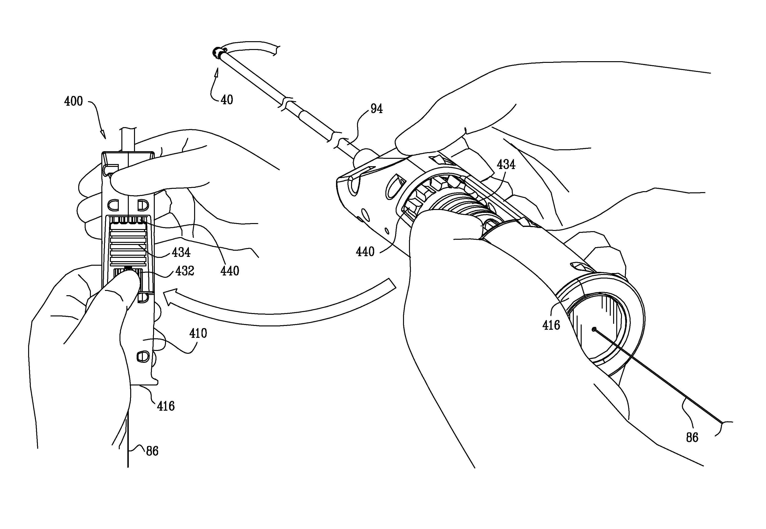
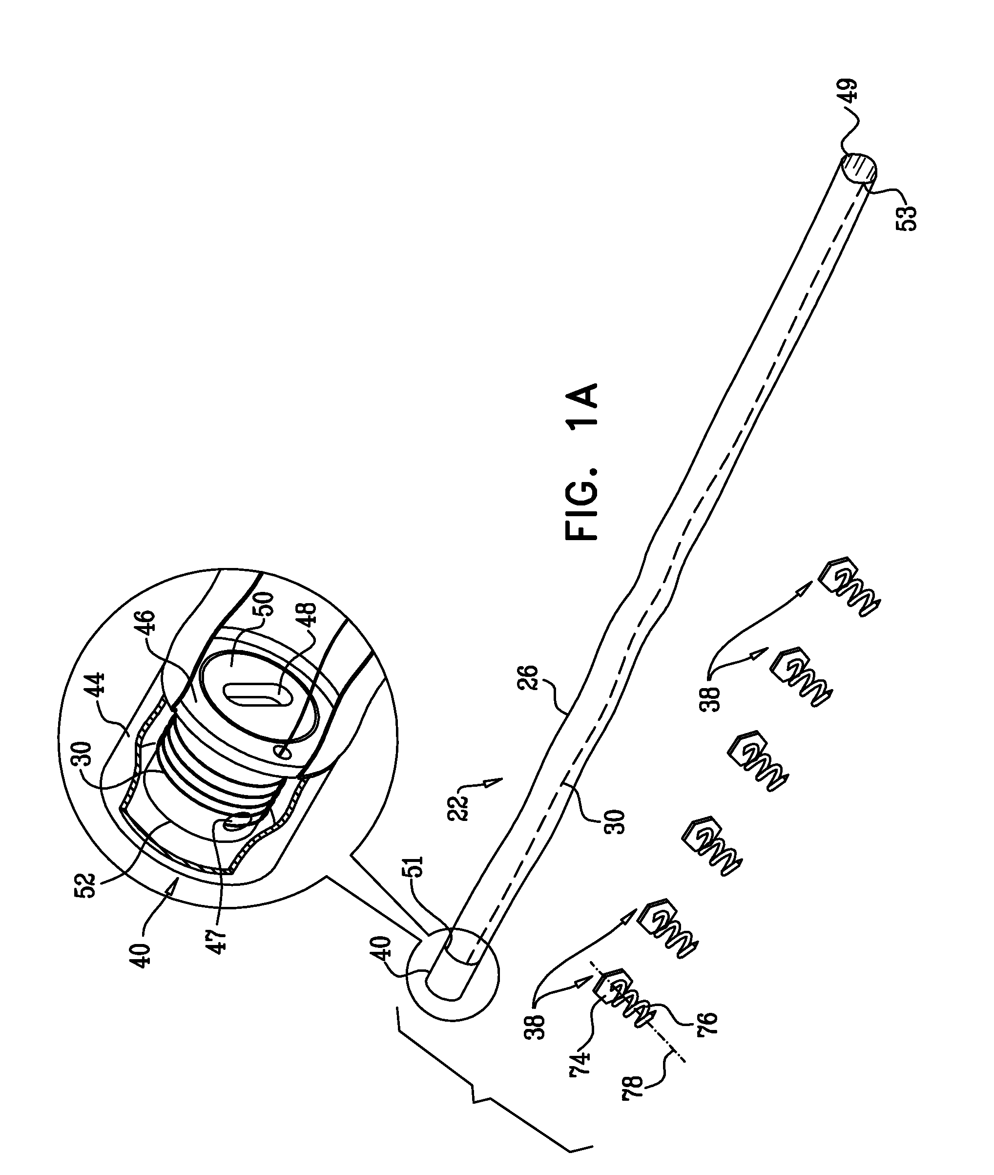
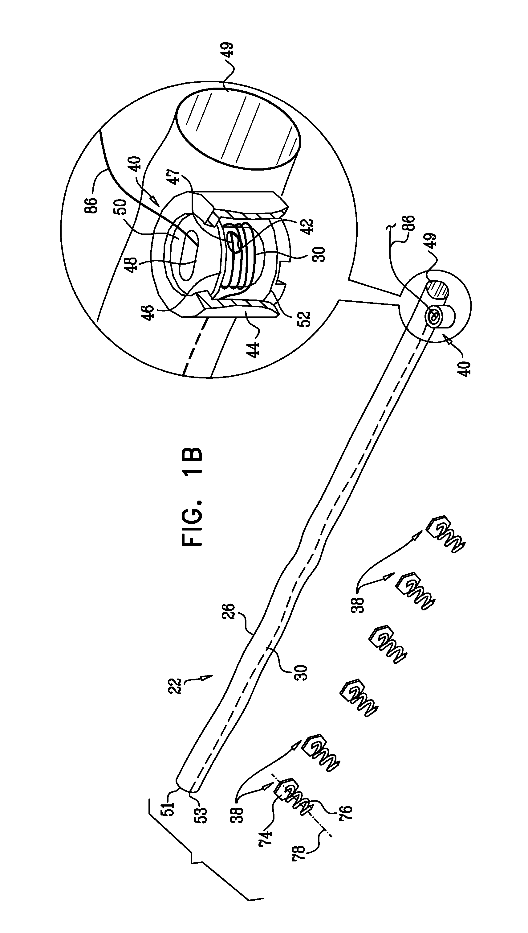
[0187]FIGS. 1-4 are schematic illustrations of a system 20 for repairing a dilated atrioventricular valve, such as a mitral valve, in accordance with an application of the present invention. System 20 comprises an adjustable partial annuloplasty ring 22, shown alone in FIGS. 1A and 1B in a non-contracted state, and an anchor deployment manipulator 24, shown alone in FIG. 2. Annuloplasty ring 22 comprises a flexible sleeve 26. Anchor deployment manipulator 24 is advanced into sleeve 26, as shown in FIGS. 3 and 4, and, from within the sleeve, deploys anchors 38 through a wall of the sleeve into cardiac tissue, thereby anchoring the ring around a portion of the valve annulus.

[0188]FIGS. 1A and 1B are schematic illustration of annuloplasty ring 22 in a non-contracted state, in accordance with respective applications of the present invention. Sleeve 26 is typically configured to be placed only partially around the valve annulus (i.e., to assume a C-shape), and, once anchored in place, to...


PUM


Abstract

Apparatus is provided that includes an implant structure, which includes a contracting mechanism, which includes a rotatable structure, arranged such that rotation of the rotatable structure contracts the implant structure. A longitudinal member is coupled to the contracting mechanism. A tool for rotating the rotatable structure is configured to be guided along the longitudinal member, to engage the rotatable structure, and to rotate the rotatable structure in response to a rotational force applied to the tool. Other embodiments are also described.

Description

CROSS-REFERENCE TO RELATED APPLICATIONS[0001]The present application is a continuation-in-part of: (a) U.S. patent application Ser. No. 12 / 435,291, filed May 4, 2009; (b) U.S. patent application Ser. No. 12 / 437,103, filed May 7, 2009; and (c) U.S. patent application Ser. No. 12 / 548,991, filed Aug. 27, 2009. The present application is related to a US patent application filed on even date herewith, entitled, “Deployment techniques for annuloplasty ring.” All of the above-mentioned applications are assigned to the assignee of the present application and are incorporated herein by reference.FIELD OF THE APPLICATION[0002]Some embodiments of the present invention relate in general to valve repair, and more specifically to repair of an atrioventricular valve of a patient.BACKGROUND OF THE APPLICATION[0003]Ischemic heart disease causes mitral regurgitation by the combination of ischemic dysfunction of the papillary muscles, and the dilatation of the left ventricle that is present in ischemi...

Claims


Application Information

Patent Timeline
Patent Type & Authority Applications(United States)
IPC IPC(8): A61F2/24
CPCA61B17/0401A61F2250/0004A61B17/068A61B2017/00243A61B2017/0409A61B2017/0414A61B2017/0441A61B2017/0464A61B2017/0496A61B2017/0647A61B2017/0648A61B2017/0649A61B2017/12095A61B2017/2923A61F2/2445A61F2/2457A61F2/2466A61F2002/30537A61F2220/0016A61B17/064A61B17/072A61B2017/0443A61F2/2409A61F2/2412A61F2/2451A61B17/00234A61F2/2436
Inventor ZIPORY, YUVALHAMMER, TALGROSSGROSS, AMIRCABIRI, OZMAISANO, FRANCESCOMILLER, ERAN
Owner VALTECH CARDIO LTD
Why Eureka
Try Eureka