
Single shaft combined cycle power plant start-up method an single shaft combined cycle power plant

a combined cycle and power plant technology, applied in the direction of engine starters, machines/engines, turbine/propulsion engine ignition, etc., can solve the problems of increased installation cost of plants, increased cost, and undesirable power plants

Active Publication Date: 2010-11-11
KK TOSHIBA
View PDF5 Cites 41 Cited by
  • Summary
  • Abstract
  • Description
  • Claims
  • Application Information

AI Technical Summary

Benefits of technology

[0021]According to an aspect of the present invention, there is presented a single shaft combined cycle power plant comprising: a gas turbine that is driven by combustion gas and discharges exhaust gas; an exhaust heat recovery boiler that uses the exhaust gas from the gas turbine as a heat source and includes a high-pressure drum for generating high-pressure steam and a low-pressure drum for generating low-pressure steam having a pressure lower than that of the high-pressure steam; a high-pressure steam turbine that is coaxially arranged with the gas turbine and driven by the high-pressure steam fed from the high-pressure drum via a high-pressure steam control valve; a low-pressure steam turbine that is coaxially arranged with the high-pressure steam turbine; a power generator that is coaxially arranged with the low-pressure steam turbine; a low-pressure turbine steam supply pipe that has a low-pressure main steam control valve and feeds the low-pressure steam from the low-pressure drum to the low-pressure steam turbine via the low-pressure main steam control valve; a start-up bo

Problems solved by technology

A first problem is that plant installation cost is increased to make the power plant undesirable from an economic view point.
The installation of the pressure reduction device and temperature reduction device leads to increased cost to adversely affect economic efficiency.
This valve is designed to control a large flow of high temperature, high-pressure steam and is therefore unsuitable for control of a small flow of steam performed at the time of starting-up the single shaft combined cycle power plant.
In this regard, economic efficiency is adversely affected.
A second problem is that it is difficult to apply a steam cooling method as a cooling method of a gas turbine high temperature part.
The present inventors have found that a use of the steam cooling type gas turbine as a component of the single shaft combined cycle power plant makes it very difficult to apply the start-up method of Patent Document 2.
Therefore, the auxiliary steam is not allowed to flow in the high-pressure steam turbine (that is, the auxiliary steam cannot be fed to the high-pressure steam turbine) in a state where the pressure relationship is reversed.
Thus, the start-up device based on this assumption cannot function.
However, as described above, an auxiliary boiler for supplying the high-pressure steam is generally expensive.
Further, an increase in the pressure inevitably incurs an increase in the steam temperature.
Thus, considering a fact that a pressure reduction device and a temperature reduction device need to be provided for multiple use purposes (e.g., for use as gland steam or deaeration steam) of the auxiliary steam, adoption of high-pressure auxiliary steam having a pressure far exceeding 0.7 MPa is not practical.
A third problem is that in the case where hot start-up is performed during DSS (Daily Start-up & Stop) operation, reverse mismatch phenomenon occurs between the metal temperature of the high-pressure steam turbine and auxiliary steam temperature.
If the hot start-up is performed in this reverse mismatch state, the steam turbine may be broken.
Therefore, the high-pressure steam turbine start-up method is not suitable for the hot start-up.
This imposes a fatal operational restriction on the single shaft combined cycle power plant that is easily ready for operation under DSS.

Method used


Image

  • Single shaft combined cycle power plant start-up method an single shaft combined cycle power plant
  • Single shaft combined cycle power plant start-up method an single shaft combined cycle power plant
  • Single shaft combined cycle power plant start-up method an single shaft combined cycle power plant

Examples


first embodiment

Modification of First Embodiment

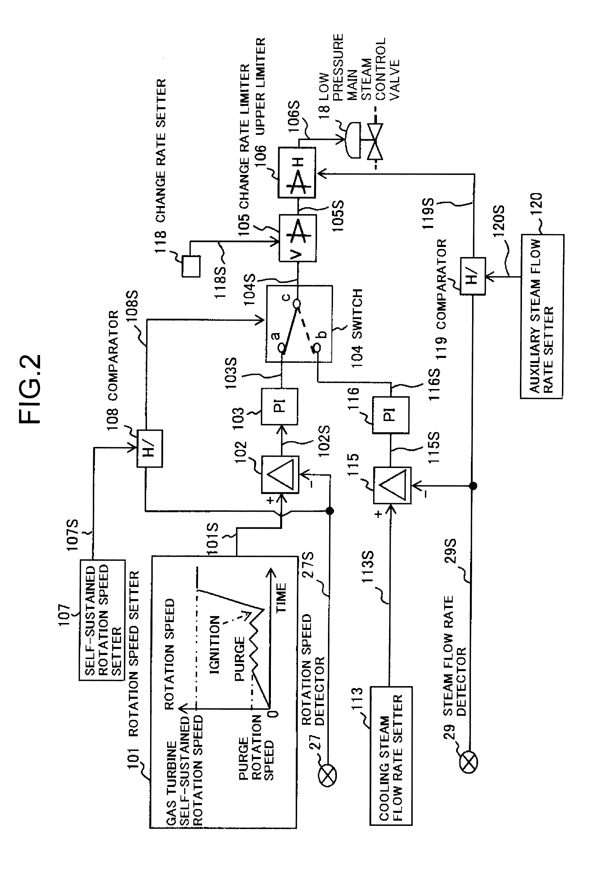
[0140]Although the flow rate of the steam passing through the low-pressure main steam control valve 18 is directly detected using the flow rate detector (flow rate transmitter) 29 in the first embodiment described above, the present invention is not limited to this. For example, as shown in FIG. 5, a configuration may be employed in which the valve opening degree of the low-pressure main steam control valve 18 is detected by a valve opening degree detector (valve opening degree sensor) 43, and the detected valve opening degree signal 43S is inputted to a function generator 44. In the function generator 44, a relationship between the valve opening degree 43S and the flow rate 44S is set in advance and calibrated. Then, the function generator 44 can calculate the flow rate of the steam passing through the low-pressure main steam control valve 18 in an indirect manner.

second embodiment

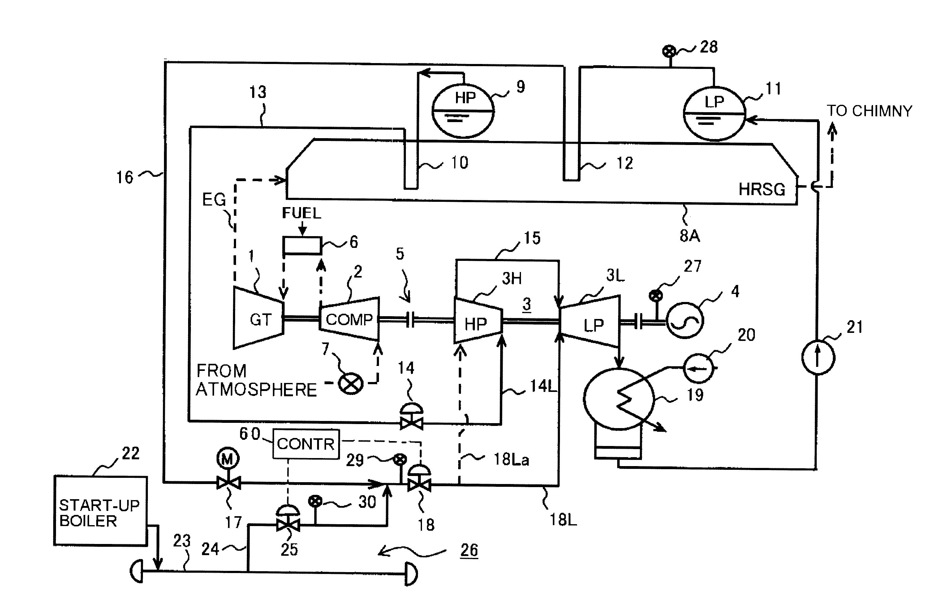
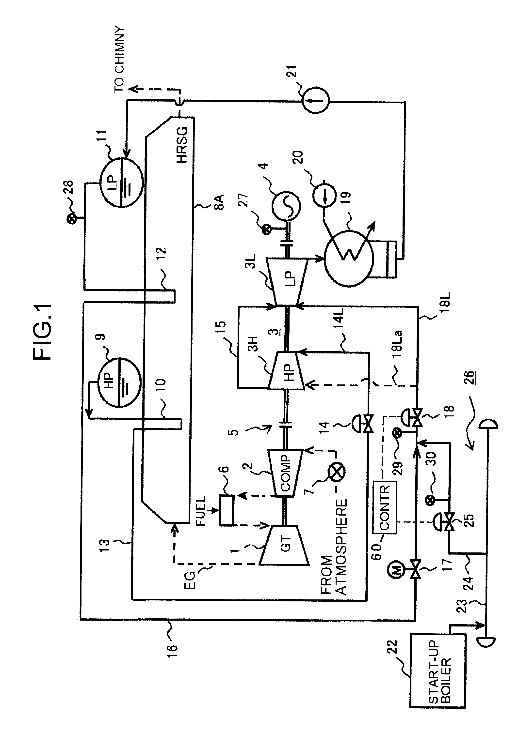
[0141]FIG. 6 is a system diagram showing the main part of the single shaft combined cycle power plant according to a second embodiment of the present invention.

[0142]The first embodiment is a single shaft combined cycle power plant constituted by two-pressure with high and low steam system pressures; while the second embodiment is a single shaft combined cycle power plant constituted by three-pressure with high, intermediate and low steam system pressures.

[0143]As shown in FIG. 6, as compared to the exhaust heat recovery boiler (HRSG) 8A of FIG. 1, an exhaust heat recovery boiler (HRSG) 8B according to the second embodiment further includes an intermediate pressure drum 31 that generates intermediate pressure steam having a pressure value lower than that of the high-pressure steam and higher than that of the lower pressure steam. The HRSG 8b also includes an intermediate pressure superheater 32 that superheats the intermediate pressure steam generated in the intermediate pressure dr...

third embodiment

[0151]FIG. 7 is a system diagram showing the main part of the single shaft combined cycle power plant according to a third embodiment of the present invention.

[0152]In the second embodiment shown in FIG. 6, the high temperature part of the gas turbine 1, such as the stator blades or rotor blades, is not cooled especially by cooling medium. On the other hand, in the third embodiment, a so-called steam cooling method that cools the high temperature part of the gas turbine 1, such as the stator blades or rotor blades, by steam is adopted.

[0153]In the system diagram of FIG. 7 showing the main part of the single shaft combined cycle power plant, a gas turbine cooling unit 38 for cooling the high temperature part of the gas turbine 1, such as the stator blades or rotor blades, is provided between the low temperature reheat system 34 and the reheater 33. Steam in the gas turbine cooling unit 38 is led to the high temperature part of the gas turbine 1, such as the stator blades or rotor bla...


PUM


Abstract

In a start-up method of a single shaft combined cycle power plant, during a time period from when the gas turbine is started up to when rotation speed of the gas turbine reaches a rotation speed allowing self-sustained operation using the combustion gas, auxiliary steam from the start-up boiler is fed to the low-pressure steam turbine via the low-pressure turbine steam supply pipe by controlling valve opening degree of the auxiliary steam flow control valve. The low-pressure steam turbine generates a drive force. Speed-up control is performed in a unified manner for the gas turbine, the high-pressure steam turbine, the low-pressure steam turbine, and the power generator.

Description

CROSS REFERENCES TO RELATED APPLICATIONS[0001]This application is based upon and claims the benefit of priority from the prior Japanese Patent Application No. 2009-113610, filed in the Japanese Patent Office on May 8, 2009, the entire content of which is incorporated herein by reference.BACKGROUND OF THE INVENTION[0002]The present invention relates to a single shaft combined cycle power plant start-up method. More specifically, the invention relates to a single shaft combined cycle power plant start-up method that uses steam fed from a steam source different from an exhaust heat recovery boiler to generate a torque in a steam turbine so as to start up a single shaft combined cycle power plant. Further, the present invention relates to the single shaft combined cycle power plant.[0003]A combined power plant is a power plant that introduces exhaust heat gas of a gas turbine into an exhaust heat recovery boiler to generate high temperature, high-pressure steam and uses the generated st...

Claims


Application Information

Patent Timeline
IPC IPC(8): F01K13/00F01K23/08
CPCF01K13/02Y02E20/16F01K23/106
Inventor ASANAKA, TOSHITADATATEISHI, MANABUTOBOU, MASAYUKIKITAGUCHI, KOUICHIITO, MASAOMATSUSHITA, TAKEHIKO
Owner KK TOSHIBA
Features
  • Generate Ideas
  • Intellectual Property
  • Life Sciences
  • Materials
  • Tech Scout
  • Unparalleled Data Quality
  • Higher Quality Content
  • 60% Fewer Hallucinations
Learn More