Optical probe

Inactive Publication Date: 2010-11-11
KONINKLIJKE PHILIPS ELECTRONICS NV
View PDF11 Cites 9 Cited by
  • Summary
  • Abstract
  • Description
  • Claims
  • Application Information

AI Technical Summary

Benefits of technology

[0006]Hence, an improved optical probe would be advantageous, and in parti

Problems solved by technology

Although helpful, these methods of guidance are far from optimal.
The resolution is limited and, furthermore, these imaging modalities can in most cases not discriminate between benign and malignant tissue.
As a result we do not know for certain that from the correct part of the tissue a biopsy is taken.
We take almost blind biopsies and even if after inspection of the tissue no cancer cells are detected, we do not know for certain that we did not simply miss the right spot to take the biopsy.
A drawback of these fibers is that they have a low exit beam numerical aperture, typically approximately 0.04.
This is quite large and thus limitin

Method used


Image

  • Optical probe
  • Optical probe
  • Optical probe

Examples


Example

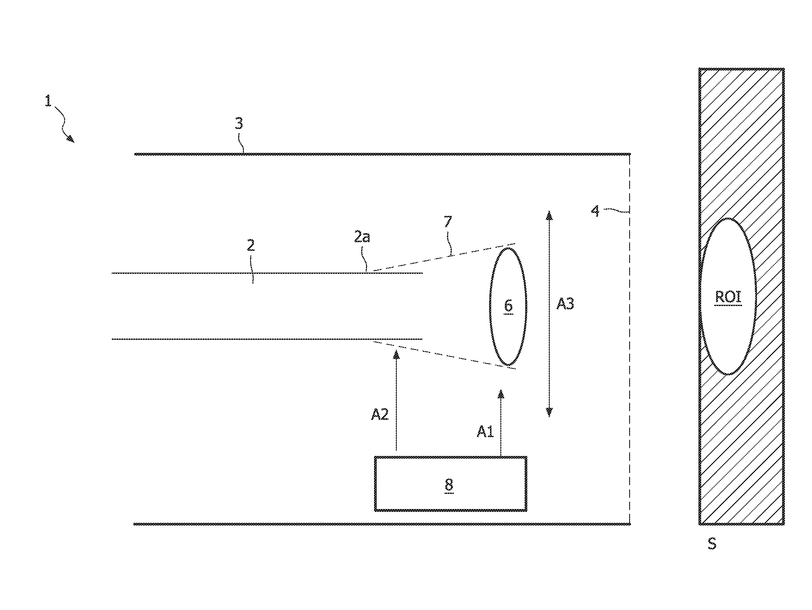
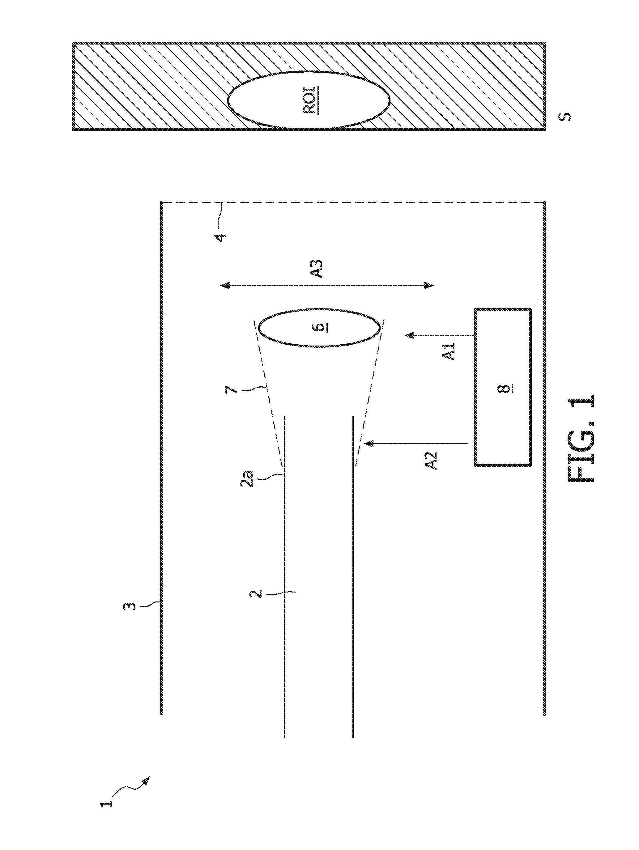
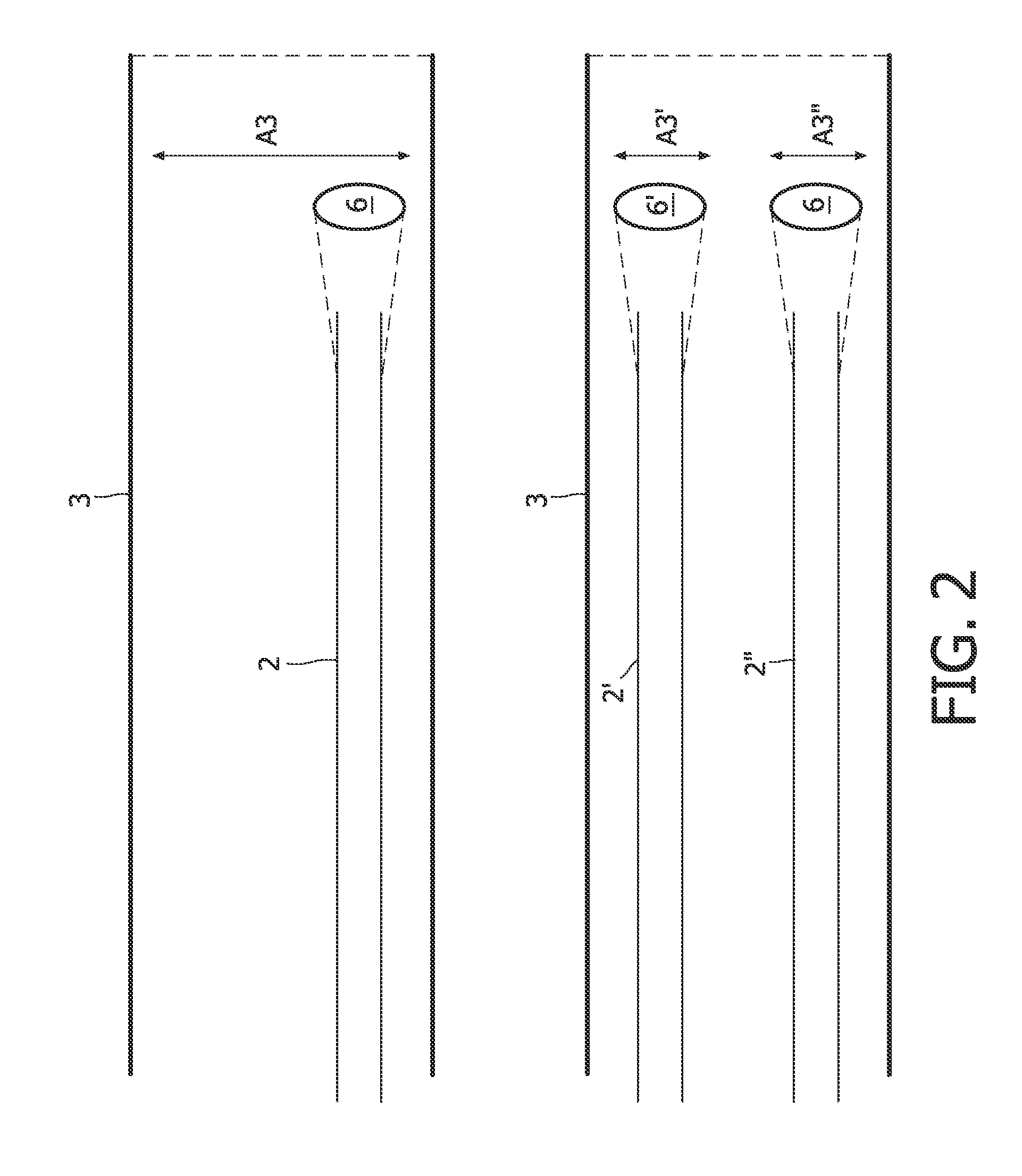
[0049]FIG. 1 is a schematic cross-sectional drawing of an optical image probe 1 according to the present invention. The optical probe 1 comprises an optical guide 2, e.g. an optical fibre, and a housing 3 having a cavity wherein the optical guide 1 can be embedded. The housing 3 has at its distal or sampling end a transparent and substantially non-focussing window 4. The window 4 can be a plane section of an optical transport glass or polymer. The window 4 is preferably non-focussing i.e. it has no optical power, but it is contemplated that the window 4 may for some applications have some focussing effect. This is however not usually the case because it may influence the performance of the lens system 6. It is nevertheless contemplated that the exit window 4 in some cases may be a field flattener lens to make the image plain flat and not curved and this requires a small amount of optical power.

[0050]A lens system 6 is rigidly coupled to an end portion 2a of the optical guide 2. The ...


PUM


Abstract

The present invention relates to an optical probe (1) with an optical guide (2), e.g. an optical fibre, and a lens system (6) rigidly coupled to an end portion (2a) of the optical guide. The probe has a housing (3) with a cavity for the optical guide, the housing having at its distal end a transparent window (4), the window having an insignificant optical power as compared to the optical power of the said lens system (6). Actuation means (8) displaces the 5 lens system so as to enable optical scanning of a region of interest (ROI). The invention is particularly suited for miniature applications e.g. for in-vivo medical application. By attaching the lens system (6) to the optical guide (2) via the mount (7), the field of view (FOV) of the optical probe (1) may be determined directly by the transverse stroke of the optical fibre (2). Hence only a relatively small stroke is required. The field of view is thus 10 effectively no longer limited by the transverse stroke. The optical probe is especially advantageous for non-linear optical imaging where the optical guide may be an optical fibre with a relatively low exit numerical aperture.

Description

FIELD OF THE INVENTION[0001]The present invention relates to an optical probe suitable for miniature applications, e.g. in-vivo medical inspections and procedures or in industrial inspections, for instance inspection of food or small devices. The invention also relates to a corresponding imaging system and a method for imaging with such an imaging system.BACKGROUND OF THE INVENTION[0002]For correct diagnosis of various diseases, e.g. cancer, biopsies are often taken. This can either be via a lumen of an endoscope or via needle biopsies. In order to find the correct position to take the biopsy, various imaging modalities are used such as X-ray, MRI and ultrasound. In case of e.g. prostate cancer in most cases the biopsy is guided by ultrasound. Although helpful, these methods of guidance are far from optimal. The resolution is limited and, furthermore, these imaging modalities can in most cases not discriminate between benign and malignant tissue. As a result we do not know for certa...

Claims


Application Information

Patent Timeline
IPC IPC(8): G01J1/58G01J1/00G02B26/10
CPCA61B1/00096A61B1/00165A61B5/0084A61B1/0019A61B5/0062A61B1/00183
Inventor HENDRIKS, BERNARDUS HENDRIKUS WILHELMUSBIERHOFF, WALTHERUS CORNELIS JOZEFBRAUN, AUGUSTINUS LAURENTIUSMIHAJLOVIC, NENAD'T HOOFT, GERT
Owner KONINKLIJKE PHILIPS ELECTRONICS NV
Why Eureka
Try Eureka