Method of measuring mechanical fatigue in turbine-generator rotors

a technology of mechanical fatigue and turbine generator, which is applied in the direction of electric generator control, liquid fuel engine, instruments, etc., can solve the problems of affecting the proper operation of power plants, affecting the security of power plants, and bringing critical damage to the shaft of large capacity units, so as to reduce economic losses, improve transmission network security, and social benefits great

Active Publication Date: 2010-11-11
BEIJING SIFANG JIBAO AUTOMATION
View PDF8 Cites 13 Cited by
  • Summary
  • Abstract
  • Description
  • Claims
  • Application Information

AI Technical Summary

Benefits of technology

[0012]The present invention utilizes the TSR and TMaster to protect the units when torsional oscillation occurs. This invention also avoids the situation that all the units or most of the units are tripped when each TSR trips separately. The present invention reduces great economic loss for the power plant, An example, a 600 MW unit will cost millions of RMB to restart a tripped turbine generator, otherwise, the loss of the unit output during the generators are tripped is huge, if the security level of transmission network is improved, it will bring great social benefit and economic benefit.

Problems solved by technology

Because of the application of these two advanced technology in power transmission networks, subsynchronous resonance occurs as a new hazard that will do harm to the grid and impact the security of power plants proper operation.
According to the problem of subsynchronous resonance, we can utilize the subsynchronous damping control or blocking filter to increase SSR severity, but the largest hazard of subsynchronous resonance is the critical damage it brings to the large capacity unit's shaft.
This kind of accident will also bring huge loss, no matter the personal injuries or the equipment damages, to the stability of the regional network.
To lose numerous high-capacity generators at the same time will do great harm to the regional transmission networks.

Method used


Image

  • Method of measuring mechanical fatigue in turbine-generator rotors
  • Method of measuring mechanical fatigue in turbine-generator rotors
  • Method of measuring mechanical fatigue in turbine-generator rotors

Examples


Embodiment Construction

[0017]The following paragraphs provide a further introduction of the invention's technical scheme according to the attached figures and cases.

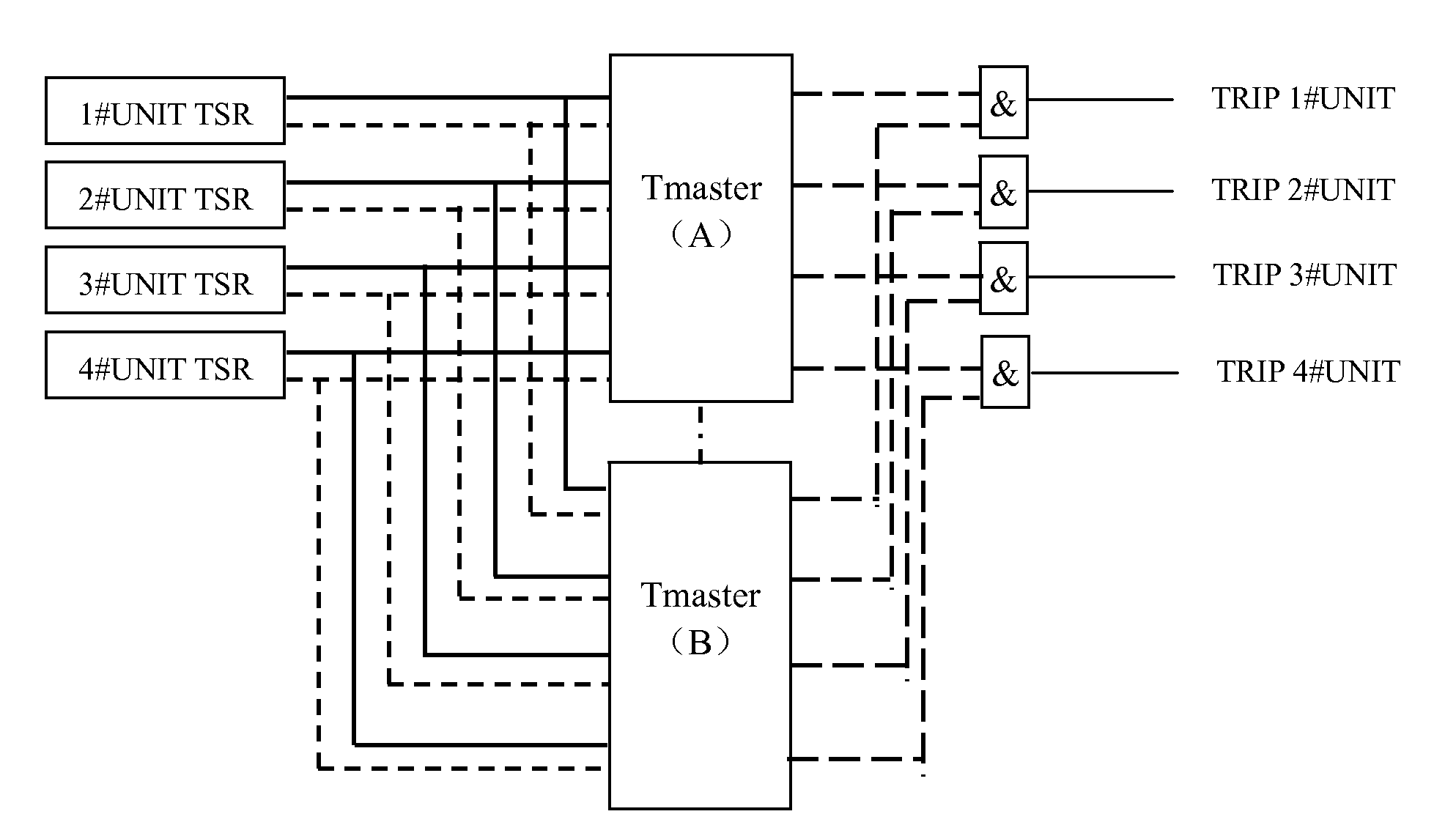
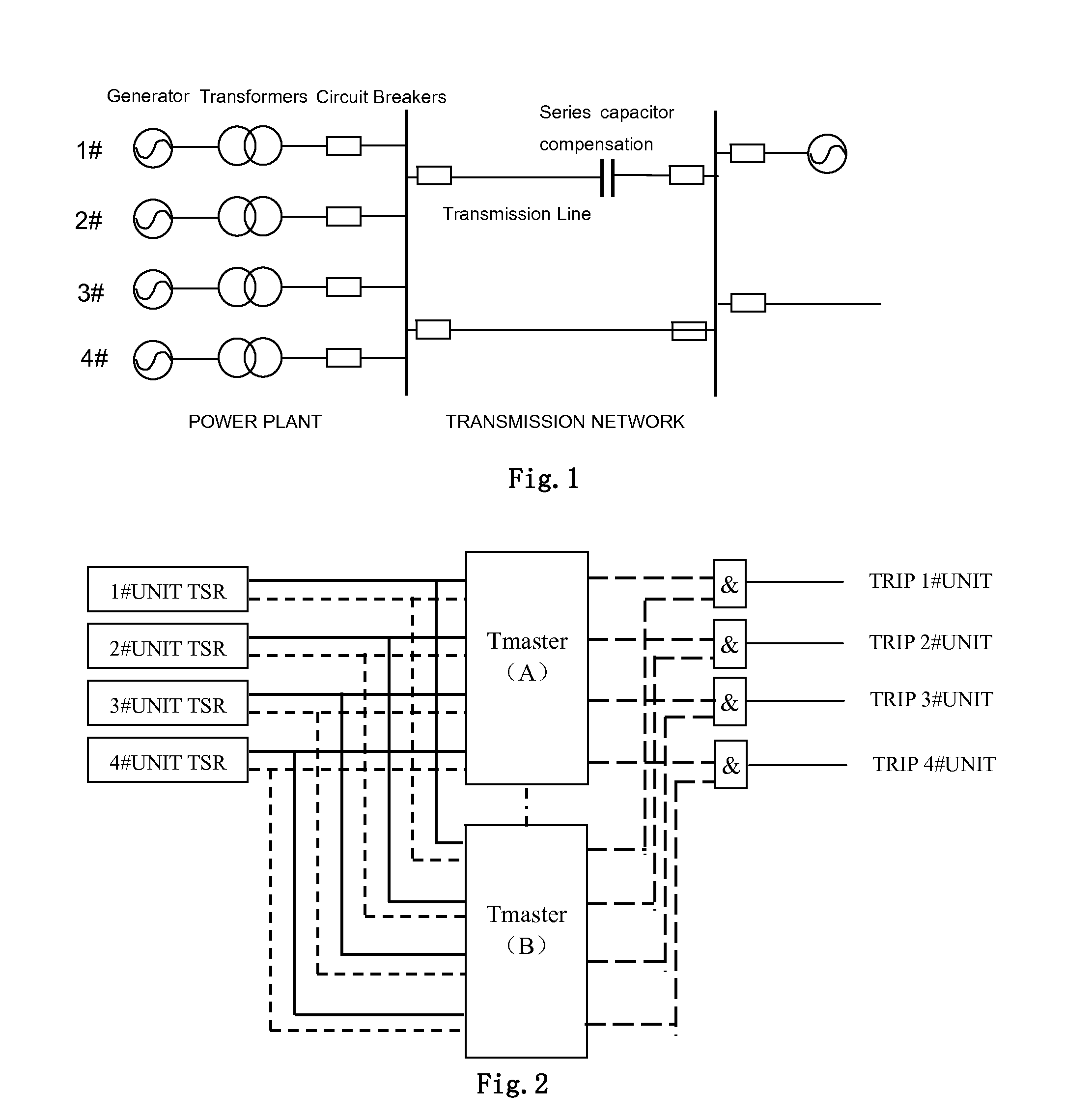
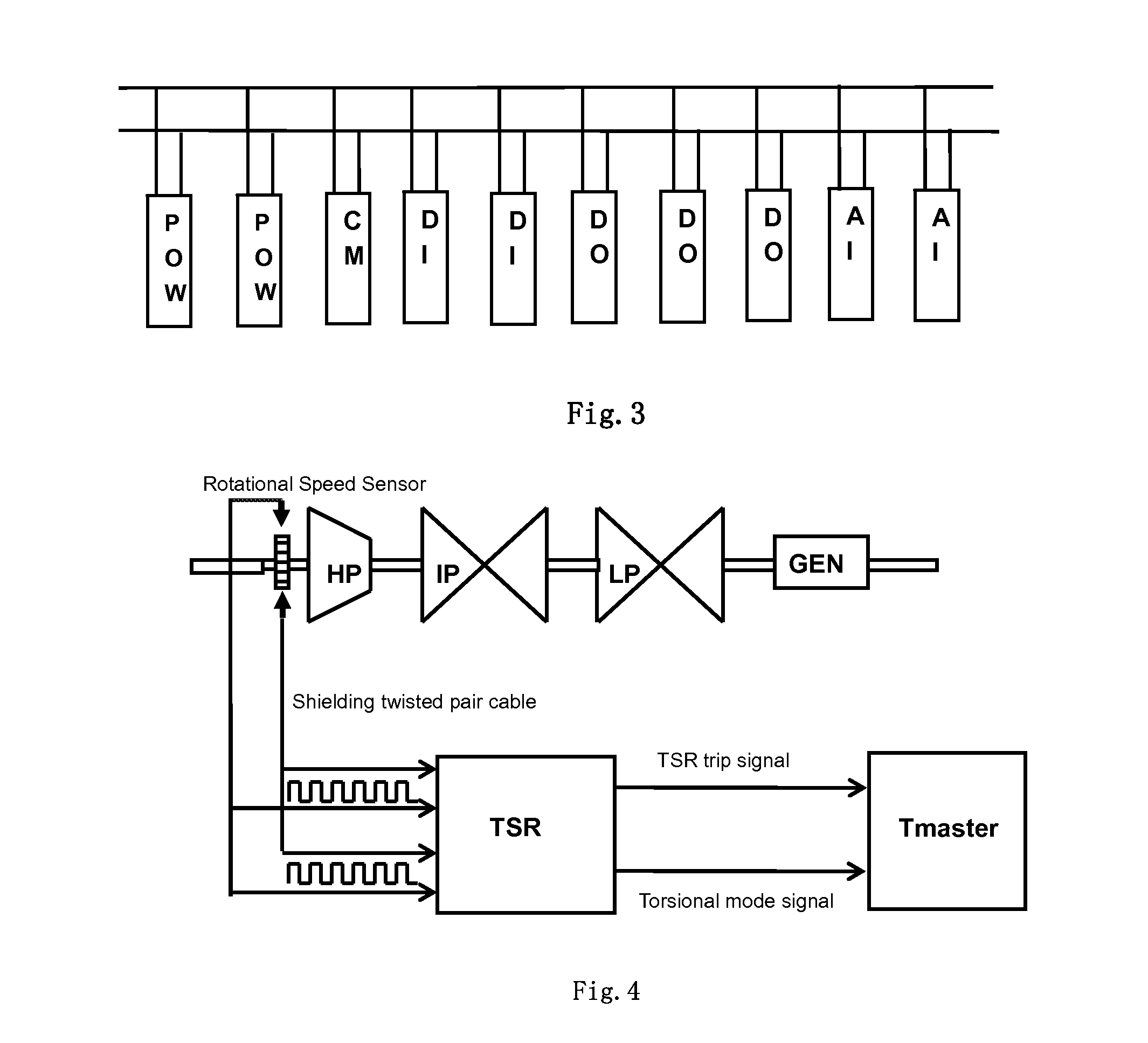
[0018]The coordinated control method of TSR in large power plant mentioned in this invention, the method's purpose is to implement a coordinated control group composed by each unit's TSR in one power plant; this group can be divided into 2 layers, TSR and TMaster. TSR implements the unit's torsional oscillation monitoring and shaft fatigue real-time calculation independently, TSR also judges whether the trip command should be sent according to the predetermined criterions and fixed value. TMaster provides real-time monitoring of each unit's operating status and output. TMaster also provides online real-time optimization strategy that implements TSR and TMaster's coordinated operation to utilize the selective trip. The coordinated control group and coordinated control method will be introduced in the following paragraphs:

[0019]Coordinated contr...


PUM


Abstract

The present invention relates to the coordinated control method of torsional stress relay in large thermal power plants' generators (300 MW and above), which will be adopted when shaft torsional oscillations occur. This invention also publishes a method of realizing selective trip the generators and the trip criterions which are implemented by the torsional stress relay and coordinated control master station (Tmaster). Tmaster will real-time monitor the operating status of the generators and TSR, TMaster will also real-time generate a trip priority level sequencing by analyzing the unit output.When generators occur subsynchronous resonance and shaft torsional oscillation, this method can ensure that TSR will trip some generators of the power plant according to the real-time generated trip strategy to inhibit the shaft torsional oscillation and safeguard the units. This method can also avoid the tremendous economic loss caused by tripping all the generators, and that will reduce the hazard to the transmission grid.

Description

FIELD OF THE INVENTION[0001]This invention is related to the field of power system, large thermal power plant, and industries which need steam turbine-generators, especially the coordinated control method of Torsional Stress Relays.BACKGROUND OF THE INVENTION[0002]With the construction of the ultra high voltage transmission grid, transmission technology of bulk power and long distance has been widely applied in China. In order to solve the problem existed in improving the transmission ability of large capacity unit, the technology of series capacitor compensation (including controllable series capacitor compensation, TCSC) has been largely applied. Otherwise, HVDC Transmission technology has been utilized in regional transmission grids to solve the stability problem of the large transmission grid, and that will form an AC-DC mixed transmission mode. Because of the application of these two advanced technology in power transmission networks, subsynchronous resonance occurs as a new ha...

Claims


Application Information

Patent Timeline
Patent Type & Authority Applications(United States)
IPC IPC(8): H02H7/06
CPCF01D21/003F05D2260/96F05D2260/80F02C9/00
Inventor JIAO, SHAOHUAZHANG, TAOLIU, QUANLIANG, XINYANLI, YUANSHENG
Owner BEIJING SIFANG JIBAO AUTOMATION
Why Eureka
Try Eureka