Heat Engine System

a technology of heat engine and heat pump, which is applied in the direction of machines/engines, indirect heat exchangers, lighting and heating apparatus, etc., can solve the problems of reducing the efficiency of the heat engine, not being able to operate the heat engine according to the ideal carnot, and being unsatisfactory, so as to reduce the melting temperature of the volume of material

Inactive Publication Date: 2010-11-18
COMMONWEALTH SCI & IND RES ORG +1
View PDF1 Cites 74 Cited by
  • Summary
  • Abstract
  • Description
  • Claims
  • Application Information

AI Technical Summary

Benefits of technology

[0035]In an embodiment, the pressure at the inlet to the expander is the pressure to which the first component is compressed in the compressor, less any losses in the system therebetween. Compression of the first component of the working fluid also increases its temperature.
[0112]In an embodiment, one of the materials in the mixture of materials of the or each volume is for improving the heat transfer of the or each volume of material. Such a material may be graphite.
[0114]In one such embodiment, aluminium is mixed with silicon to reduce the melting temperature of the volume of material.

Problems solved by technology

In practice, however, it is not possible to operate a heat engine according to the ideal Carnot cycle because none of the process steps are truly “reversible”.
An alternative, but not as efficient, cycle for operating a heat engine is the Rankine cycle.
The reason for doing this is that whilst it reduces the efficiency of the heat engine, in practice, it is difficult for a pump to handle a mixture of liquid and vapour as is the case in the Carnot cycle.
This means that the heat must be transferred to the vapour as it undergoes an expansion process (which is difficult to carry out in practice), as opposed to the Rankine cycle in which the vapour is superheated at a constant pressure.
In practice, however, heat engines operating according to the Rankine cycle have a lesser efficiency than the maximum theoretical efficiency (ie. the efficiency of the ideal Rankine cycle) for similar reasons to those outlined for the Carnot cycle above.
However, the efficiencies of all real heat engines remain significantly limited, and improvements which increase the efficiency of power and refrigeration production are still sought.

Method used


Image

  • Heat Engine System
  • Heat Engine System
  • Heat Engine System

Examples


example

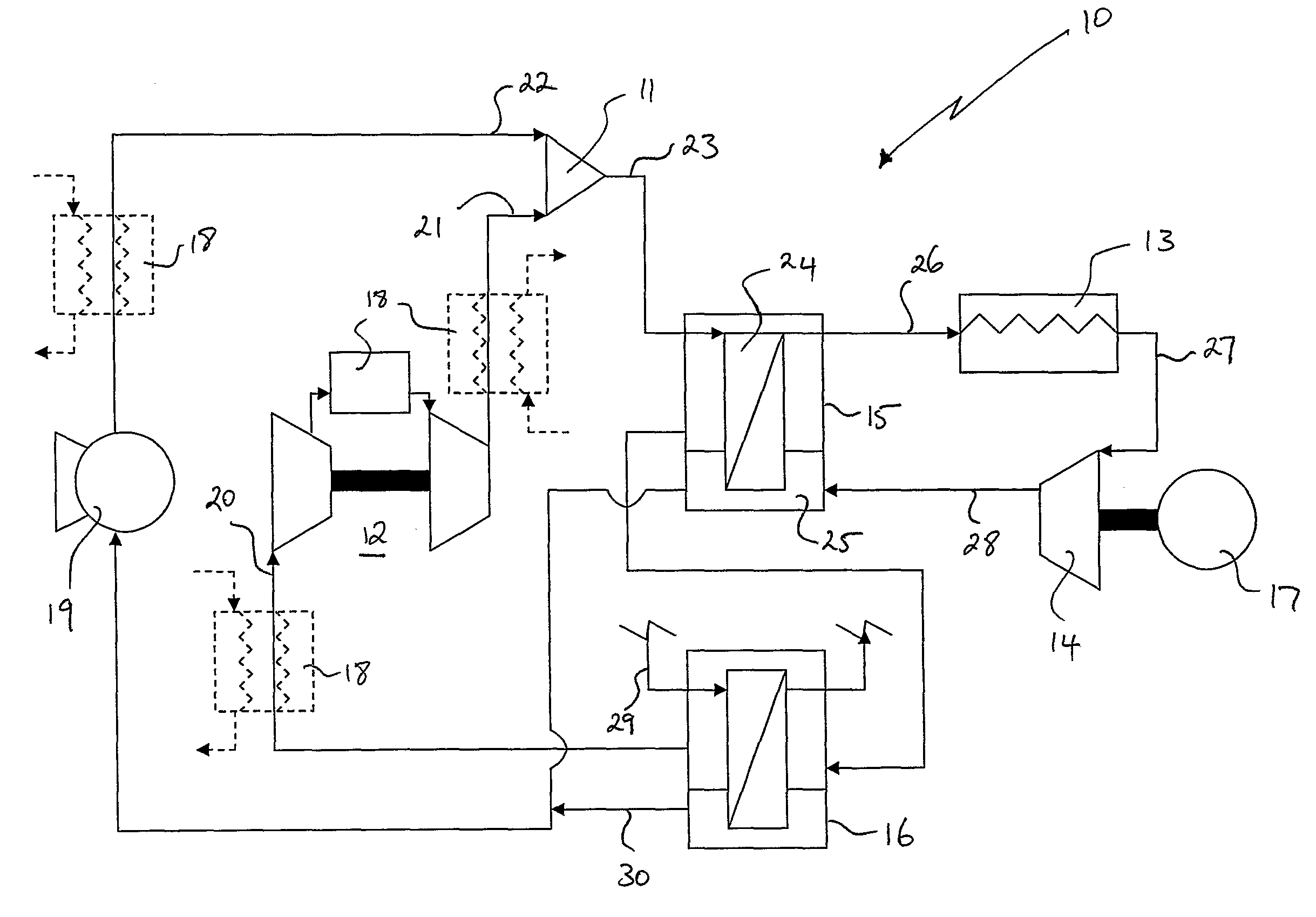
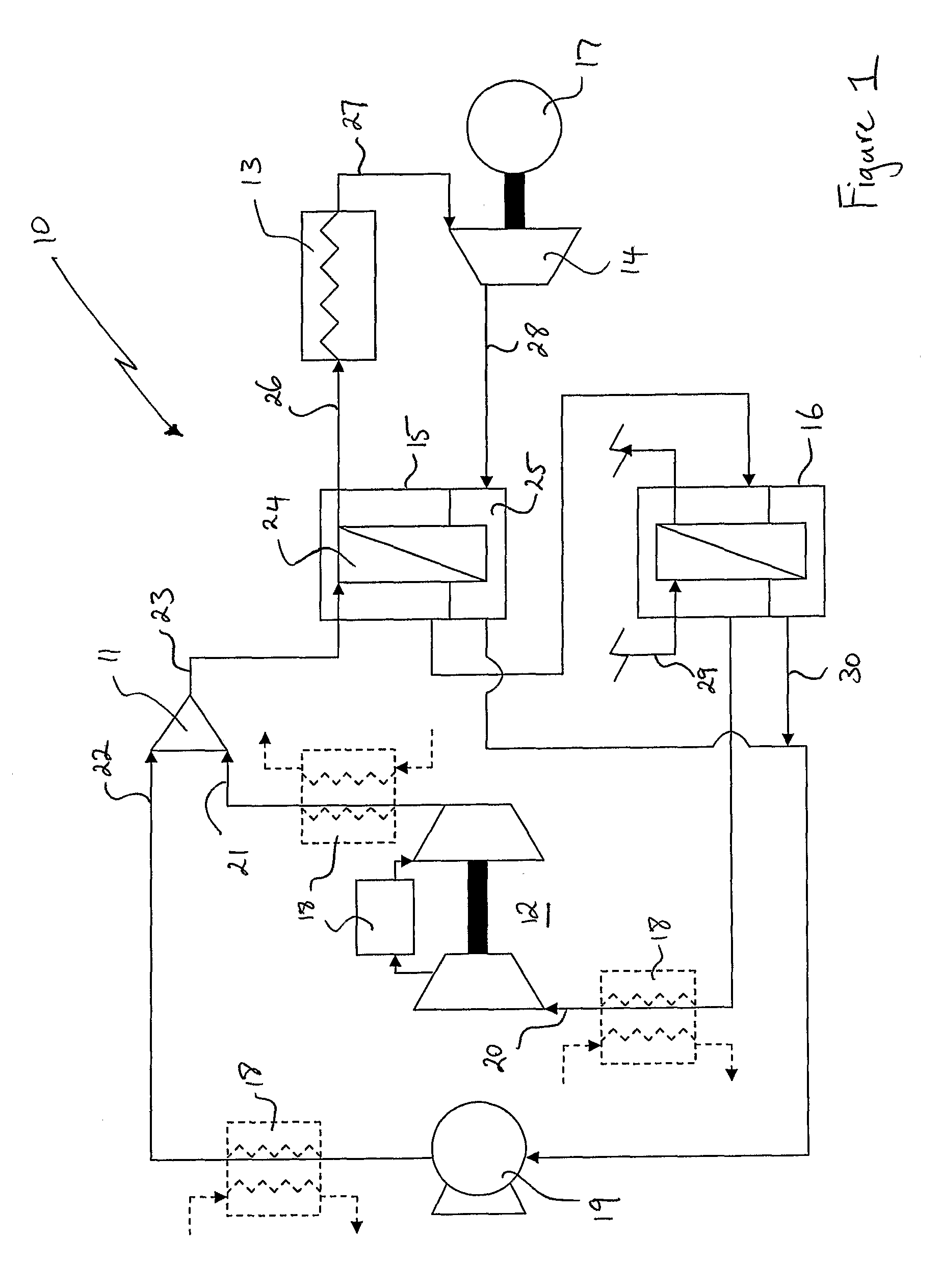
[0205]A model of a heat engine system according to embodiments of the present invention was constructed in HYSYS®. FIG. 3 provides a schematic view of the model. The model was prepared on the basis of an approximately 1:1 mass flow ratio of nitrogen as the first component and water as the second component. Other parameters assumed for the model include:[0206]an ambient temperature of 35° C. (for Queensland ambient temperature conditions)[0207]compression ratio for the compressor of 6.2:1[0208]Compressor efficiency of 85%[0209]Expander efficiency of 85%[0210]Pressure drops of 5 kPa for the apparatus, 30 kPa for the boiling side of the recuperator, 20 kPa for the heater, 300 Pa for the condensing side of the recuperator.[0211]Exit temperature for the recuperator condensing side of 60° C.

[0212]Table 1 below sets out the conditions at points A-I in the system as indicated on FIG. 3.

TABLE 1AB(Nitrogen)(Water)CDEFGHITemperature35.0035.00273.545.91617.61100742.960.0035.00(° C.)Pressure100....


PUM


Abstract

A heat engine system for producing work by expanding a working fluid comprising first and second components, the system comprising, an apparatus for combining the second component of the working fluid as a liquid with the first component, the first component being a gas throughout the system, a compressor for compressing the first component, a pump for compressing at least most of the second component, a heater for heating the first and second components, an expander for expanding the first and second components to produce the work, and a recuperator for transferring at least some of the energy of the working fluid from the outlet of the expander, to the working fluid from the outlet of the apparatus, wherein a substantial portion of the energy transferred in the recuperator is at least a portion of the latent heat of the second component from the outlet of the expander.

Description

FIELD OF THE INVENTION[0001]The present invention relates to a heat engine system and to a method for producing work.BACKGROUND OF THE INVENTION[0002]A heat engine is a system arranged to convert thermal energy to mechanical work. The heat engine does this by transferring energy from a high temperature heat source (TH) to a low temperature heat sink (TL). The efficiency of any heat engine is understood to be determined by, amongst other factors, the difference in temperature between the heat source and the heat sink. The efficiency of various heat engines currently in use range from 3% to about 60%. Most automotive engines have an efficiency of approximately 25% and supercritical coal-fired power stations have an efficiency of approximately 35-41%.[0003]Because the efficiency of any heat engine is understood to be dependent on the temperature gradient between the heat source and heat sink, many attempts have been made to increase heat engine efficiencies by increasing this temperatu...

Claims


Application Information

Patent Timeline
Patent Type & Authority Applications(United States)
IPC IPC(8): F01K27/00
CPCF01K17/06F28D20/026Y02E60/145F01K21/04Y02E60/14
Inventor GLYNN, PATRICK JOSEPHBUCKLAND, COLIN
Owner COMMONWEALTH SCI & IND RES ORG
Why Eureka
Try Eureka